JLG G12-55A AccuPlace Service Manual User Manual
Page 189
9.71
G10-55A & G12-55A AccuPlace
Electrical System
FRAME LEVEL
LEFT VALVE –
OPEN CIRCUIT
33234 Voltage on UGM pin J2-11
indicates solenoid
disconnected.
N
Check for continuity through this circuit.
Inspect wiring for physical damage.
Note: An open circuit voltage of nearly
8.0V exists on this UGM pin for circuit
diagnostic purposes.
FRAME LEVEL
LEFT VALVE –
SHORT TO
BATTERY
33235 Voltage on UGM pin J2-11
indicates STB fault.
N
Check for continuity through this circuit.
Inspect wiring for physical damage.
FRAME LEVEL
LEFT VALVE –
SHORT TO
GROUND
33236 Loss of current feedback on
UGM pin J3-2 while driving
coil via UGM pin J2-11.
N
Check for continuity through this circuit.
Inspect wiring for physical damage.
FRAME LEVEL
RIGHT VALVE -
OPEN CIRCUIT
33237 Voltage on UGM pin J2-22
indicates solenoid
disconnected.
N
Check for continuity through this circuit.
Inspect wiring for physical damage.
Note: An open circuit voltage of nearly
8.0V exists on this UGM pin for circuit
diagnostic purposes.
FRAME LEVEL
RIGHT VALVE –
SHORT TO
BATTERY
33238 Voltage on UGM pin J2-22
indicates STB fault.
N
Check for continuity through this circuit.
Inspect wiring for physical damage.
Note: The wire on the low side of the coil
provides current feedback to J3-14 and
can open circuit the electrical path to
ground to prevent current flow through the
coil (to prevent function movement).
FRAME LEVEL
RIGHT VALVE –
SHORT TO
GROUND
33239 Loss of current feedback on
UGM pin J3-2 while driving
coil via UGM pin J2-22.
N
Check for continuity through this circuit.
Inspect wiring for physical damage.
FRAME LEVEL –
CURRENT
FEEDBACK
READING TOO
LOW
33336 Current feedback on UGM
pin J3-2 > 250ma; but
difference from commanded
current while driving coil via
UGM pin J2-22 > 125ma for
1 second.
N
Check for continuity through this circuit.
Inspect wiring for physical damage.
Check the current on the Feedback wire
returning to UGM pin J3-14. This current
should read within 20ma of the value
commanded as read on the Analyzer
under Diagnostics/Ground for either Left
Stabilizer Up or Down functions;
otherwise, there is a degraded
connection. If the value does not track,
temporarily swap connections to assess
whether and how the fault follows the
wiring.
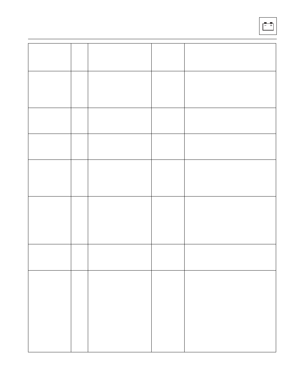
Help Message
1
DTC
Fault Condition
(for configurable items,
fault applies only if
configured)
Fault
Requires
AccuPlace
Reset?
Action(s)