4 hydraulic circuits, 1 hydraulic pressures, Hydraulic circuits – JLG G12-55A AccuPlace Service Manual User Manual
Page 95: To section 8.4, “hydraulic, Circuits, Section 8.4, “hydraulic, Hydraulic pressures
8.5
G10-55A & G12-55A AccuPlace
Hydraulic System
8.4
HYDRAULIC CIRCUITS
This section covers the hydraulic circuits and includes
listings for all hydraulic function pressures, where and
how to check those pressures and a hydraulic schematic.
Electrical and hydraulic functions are often related. Verify
that the electrical components of the circuit are
functioning properly whenever troubleshooting the
hydraulic circuit.
Always check the following before beginning to
troubleshoot a circuit that is not functioning correctly.
1. Check the hydraulic oil level in the reservoir. Oil level
should be to the middle of the sight glass with all
cylinders retracted.
2. Check hoses, tubes, fittings and other hydraulic
components for leaks, bends, kinks, interference, etc.
3. Check for air in the hydraulic system. Erratic machine
performance and/or spongy cylinder operation are
signs of air in the hydraulic system.
If air in the hydraulic system is suspected, you will
hear air leakage when hydraulic fittings are loosened
and see air bubbles in the hydraulic fluid.
Loose fittings, faulty o-rings or seals, trapped oil,
leaks, system opened for service, etc., can cause air
in the system. Determine what is causing air to enter
the system and correct it. Bleed air from the system.
8.4.1
Hydraulic Pressures
a. Checking Pressure
1. Start the machine and warm the hydraulic system to
operating temperature.
2. Shut off the machine and install a digital or a
5000 psi (345 bar) gauge to the appropriate test port
on the hydraulic manifold.
3. Start the machine, run the engine at idle and bottom
the appropriate hydraulic function. Refer to Section
8.4.1, c. “Pressure Specifications,” for the correct
pressure rating.
b. Adjusting Hydraulic Pressure
1. Shut the machine off. Remove the cap on the relief
(if necessary).
2. Start the machine and loosen the jam nut on the
relief. Turn the relief clockwise to increase pressure
or counter-clockwise to decrease pressure. Set to
the correct pressure.
3. Tighten the jam nut and recheck the pressure at full
throttle. If the reading is within specification, shut the
machine off, install the safety cap and remove the
gauge from the test port.
4. If the proper pressure cannot be set, use the
accompanying hydraulic schematic and/or the
electrical schematic to help troubleshoot and correct
the problem.
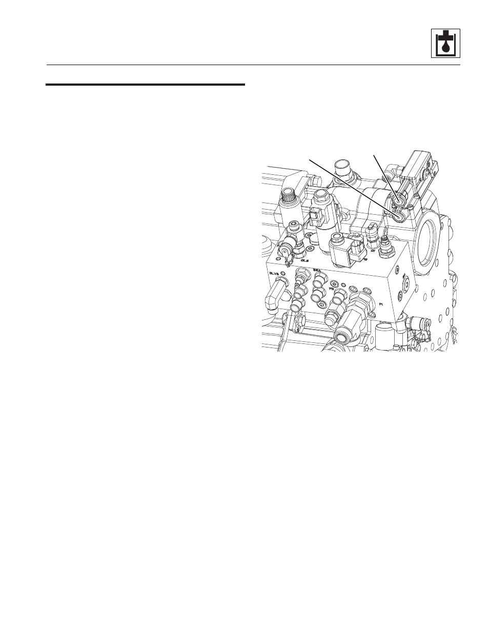
5. The Load Sense (LS) Pressure Adjustment Plug (1)
adjusts the swashplate angle (and therefore, the
system flow) to maintain a constant pressure delta
(or Margin Pressure) across an external control
valve.
6. The Pressure Compensator (PC) Adjustment Plug
(2) maintains the system pressure in the hydraulic
circuit at or below the PC setting by varying the
output flow of the pump if needed. The pump
remains at maximum displacement until the LS
control has enough margin pressure for the flow
command, or the system pressure exceeds the PC
setting.
MAP0550
2
1