4 drive shafts, 1 drive shaft inspection and service, 2 drive shaft maintenance – JLG G12-55A AccuPlace Service Manual User Manual
Page 63: 3 drive shaft removal, 4 drive shaft cleaning and drying, 5 drive shaft installation, Drive shafts, Drive shaft inspection and service, Drive shaft maintenance, Drive shaft removal
5.9
G10-55A & G12-55A AccuPlace
Axles, Drive Shafts, Wheels and Tires
5.4
DRIVE SHAFTS
5.4.1
Drive Shaft Inspection and Service
Whenever servicing the machine, conduct a visual
inspection of the drive shafts and cross and bearing
assemblies (universal joints, or U-joints). A few moments
spent doing this can help prevent further problems and
down time later.
Inspect areas where the drive shaft flange yokes and slip
yokes mount to the drive shafts. Attempt to turn each
drive shaft in both directions. Look for excessive
looseness, missing parts, cracks or other damage. Worn
or damaged drive shafts and cross and bearing
assemblies may cause an excessive amount of vibration
or noise.
5.4.2
Drive Shaft Maintenance
Refer to Section 2.4, “Fluid and Lubricant Capacities,” for
information regarding the lubrication of the grease fittings
on the drive shafts.
5.4.3
Drive Shaft Removal
Note: The drive shaft assemblies are balanced
assemblies. Mark the yoke and axle, transmission,
transfer case, and the shaft and slip yoke so that these
components can be returned to their original positions
when reinstalled. Yokes at both ends of the drive shaft
must be in the same plane to help prevent excessive
vibration.
1. Park the machine on a firm, level surface, level the
machine, fully retract the boom, lower the boom,
place the transmission control lever in (N) NEUTRAL,
engage the park brake and shut the engine OFF.
2. Place a Do Not Operate Tag on both the ignition key
switch and steering wheel, stating that the machine
should not be operated.
3. Open the engine cover. Allow the system fluids to
cool.
4. Disconnect the battery negative (-) cable from the
battery negative (-) terminal.
5. Block the wheels.
6. The drive shaft assembly is a balanced assembly.
Mark the yoke and axle, transmission and the shaft
and slip yoke so that these components can be
returned to their original positions when reinstalled.
Yokes at both ends of the drive shaft must be in the
same plane to help prevent excessive vibration.
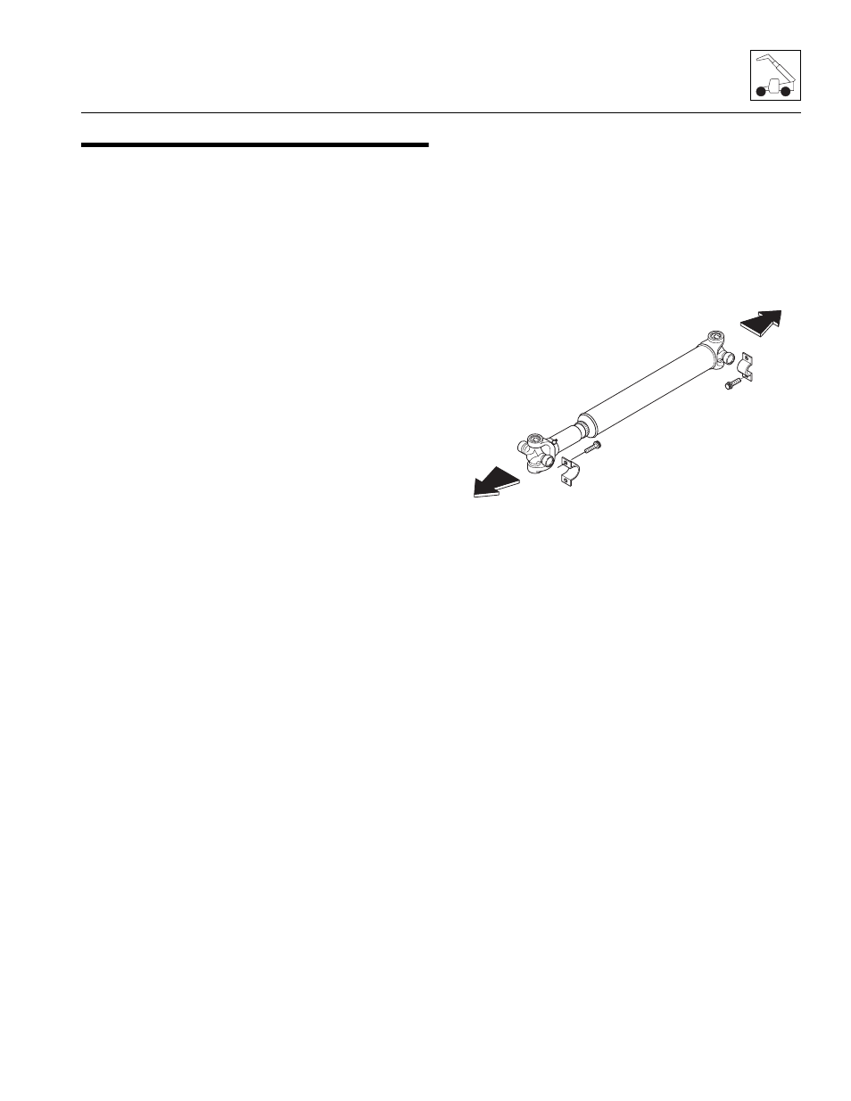
7. Remove the four capscrews and two straps securing
the bearing cross to the transmission output shaft
flange.
8. Remove the four capscrews and two straps securing
the bearing crosses to the axle.
9. Remove the front drive shaft assembly.
10. Repeat the above procedure on the second front
drive shaft and rear drive shaft.
5.4.4
Drive Shaft Cleaning and Drying
1. Disassemble and clean all parts using an approved
cleaning fluid. Allow to dry.
2. Remove any burrs or rough spots from all machined
surfaces. Re-clean and dry as required.
5.4.5
Drive Shaft Installation
1. Raise the drive shaft assembly into position. The
slip-yoke end of the drive shaft mounts toward the
axle. If reinstalling a drive shaft previously removed,
align the flange yokes according to the alignment
marks made during removal.
2. Install the four capscrews and two straps securing
the bearing crosses to the transmission.
Note: Do not re-torque strap capscrews. Replace old
capscrews with new capscrews and torque to 55-60 lb-ft
(75-81 Nm). Apply Loctite
®
242 threadlock to capscrew
threads before tightening.
3. Install the four capscrews and two straps securing
the bearing crosses to the axle.
4. Repeat the above procedure on the remaining front
drive shaft and rear drive shaft.
5. Connect the battery negative (-) cable to the battery
negative (-) terminal.
6. Close and secure the engine cover.
7. Unblock the wheels.
MT0350
To Axle
To Transmission