8 control valves, 1 lift valve, Control valves – JLG G12-55A AccuPlace Service Manual User Manual
Page 104: Lift valve
Hydraulic System
8.14
G10-55A & G12-55A AccuPlace
7. Label, disconnect and cap the hydraulic hoses
attached to the pump.
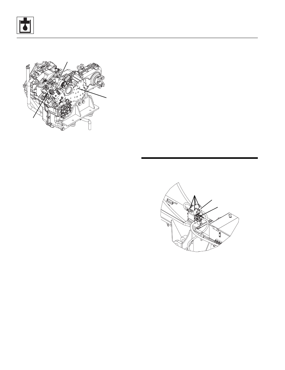
8. Remove the four bolts and lockwashers securing the
pump to the transmission (2). Remove the four bolts
securing the hydraulic manifold (3) to the pump.
Remove the o-ring located between the transmission
and the pump. Wipe up any hydraulic oil spillage.
Note: DO NOT disassemble the operating pump. The
pump is pre-set from the manufacturer. Any adjustments
or repairs performed by anyone other than an authorized
dealer could void the warranty.
b. Pump Installation
1. Place the pump and a new, oiled o-ring into position
on the transmission. Align the pump shaft with the
internal transmission gear, so that the machined
teeth mesh together.
2. Align the bolt holes with the pump mount holes.
Secure the pump to the transmission with the four
bolts and washers. Secure the hydraulic manifold to
the pump with the four bolts.
3. Uncap and connect the previously labeled hydraulic
hoses to their appropriate locations.
4. Fill the hydraulic reservoir. Refer to Section 8.6.2,
“Hydraulic Oil Reservoir Filling.”
5. Prime the pump by filling the case drain port with fresh,
filtered hydraulic oil from a clean container before
installing the case drain connector and hose.
6. Check all routing of hoses and tubing for sharp
bends or interference with any rotating members. All
tube and hose clamps must be tight.
7. Remove the 10 amp fuse from location F3 in power
distribution unit located in the engine compartment.
This will allow the engine to crank, but not start while
air is worked out of the new pump.
8. Connect a hose to the “P1” port on the pump. Direct
the open end of the hose into a fluid drip pan.
9. Turn the machine ignition switch to START and back
OFF in 3 to 5 second intervals. Monitor the open end
of the drain hose for a constant flow of fluid (no air)
while engine is cranking.
10. Once a constant flow is achieved at the open end of
the drain hose, disconnect the hose and reinstall the
10 amp fuse to location F3 in the power distribution
unit.
11. Inspect for leaks and check all fluid levels. The
hydraulic reservoir oil level must be to the middle of
the sight gauge.
c. Pump Test
Refer to Section 8.3.1, “Pressure Checks and
Adjustments.”
8.8
CONTROL VALVES
8.8.1
Lift Valve
a. Lift Valve Removal
1. Park the machine on a firm, level surface, level the
machine, fully retract the boom, raise and support the
boom, place the transmission control lever in (N)
NEUTRAL, engage the park brake and shut the
engine OFF.
2. Place a Do Not Operate Tag on both the ignition key
switch and the steering wheel, stating that the
machine should not be operated.
3. Open the engine cover. Allow the system fluids to
cool.
4. Disconnect the battery negative (-) cable from the
battery negative (-) terminal.
MAP0220
1
2
3
MY2810
2
1
SHOWN WITHOUT ACCUMULATOR
3