AEM 30-71XX Infinity Stand-Alone Programmable Engine Mangement System Full Manual User Manual
Page 373
Wiring, Pinouts and Schematics
367
© 2014 AEM Performance Electronics
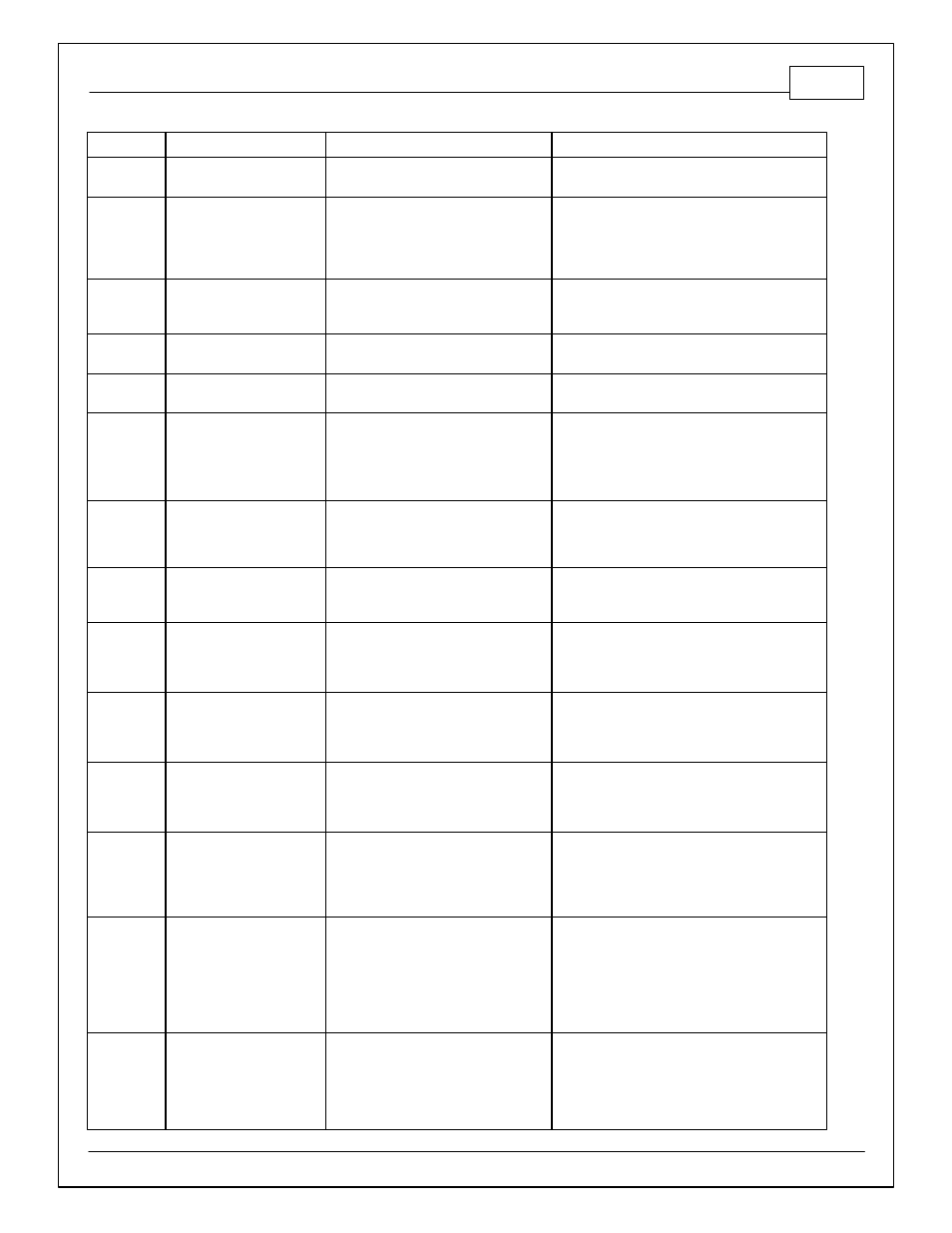
Infinity Pin
Hardware Ref.
Hardware Specification
Notes
C1-61
DBW1 Motor -_Out
5.0A max Throttle Control Hbridge
Drive
+12V to close
C1-62
DBW1 Motor +_Out
5.0A max Throttle Control Hbridge
Drive
+12V to open
C1-63
+12V_In
12 volt power from relay
12 volt power from relay. Relay must be
controlled by +12V Relay Control signal, pin C1-
47 above.
C1-64
Injector 6_Out
Saturated (P/N 30-7108) or peak and
hold, 3A max continuous (P/N 30-7106)
Injector 6
C1-65
Injector 5_Out
Saturated (P/N 30-7108) or peak and
hold, 3A max continuous (P/N 30-7106)
Injector 5
C1-66
Injector 4_Out
Saturated (P/N 30-7108) or peak and
hold, 3A max continuous (P/N 30-7106)
Injector 4
C1-67
Power Ground_In
Power Ground
Connect directly to battery ground
C1-68
+12V_In
12 volt power from relay
12 volt power from relay. Relay must be
controlled by +12V Relay Control signal, pin C1-
47 above.
C1-69
Analog_In_19
12 bit A/D, 100K pullup to 5V
0-5V analog signal. Use +5V Out pins as power
supply and Sensor Ground pins as the low
reference. Do not connect signals referenced to
+12V as this can permanently damage the ECU.
C1-70
Analog_In_18
12 bit A/D, 100K pullup to 5V
0-5V analog signal. Use +5V Out pins as power
supply and Sensor Ground pins as the low
reference. Do not connect signals referenced to
+12V as this can permanently damage the ECU.
C1-71
Analog_In_16
12 bit A/D, 100K pullup to 5V
0-5V analog signal. Use +5V Out pins as power
supply and Sensor Ground pins as the low
reference. Do not connect signals referenced to
+12V as this can permanently damage the ECU.
C1-72
Flash_Enable_In
10K pulldown
Not usually needed for automatic firmware
updates through Infinity Tuner. If connection
errors occur during update, connect 12 volts to
this pin before proceeding with upgrade.
Disconnect the 12 volts signal after the update.
C1-73
Analog_In_13
12 bit A/D, 100K pullup to 5V
0-5V analog signal. Use +5V Out pins as power
supply and Sensor Ground pins as the low
reference. Do not connect signals referenced to
+12V as this can permanently damage the ECU.
See Setup Wizard Oil Pressure page for setup
options. See OilPressure [psig] for channel
data.
C1-74
Analog_In_11
12 bit A/D, 100K pullup to 5V
0-5V analog signal. Use +5V Out pins as power
supply and Sensor Ground pins as the low
reference. Do not connect signals referenced to
+12V as this can permanently damage the ECU.
See