AEM 30-71XX Infinity Stand-Alone Programmable Engine Mangement System Full Manual User Manual
Page 237
Tuning Guide
231
© 2014 AEM Performance Electronics
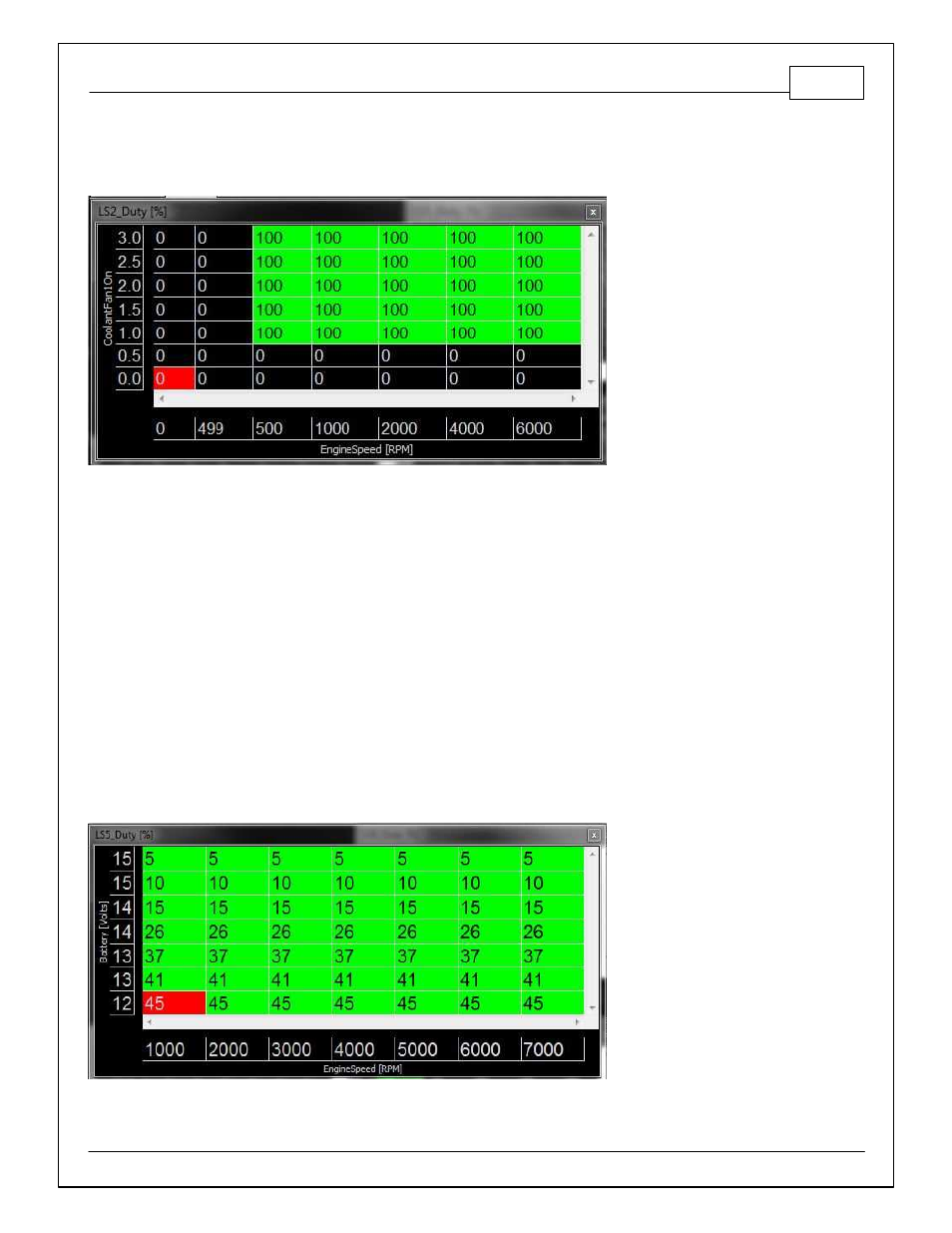
Here's an example of combining the Coolant Fan control function with a LS Duty table to add an
RPM dependent condition:
There is a trick or two here. To trigger a relay, we set the duty cycle to 100 when we want the
relay to turn on, and 0 when we want the relay to turn off. In this case, we want the relay to turn on
when the 'CoolantFan1On' condition is 1. Note that the second y-axis row is set to '0.5' and the
third row is set to '1.0'. This is because the channel 'CoolantFan1On' is an internal logic flag that
goes from 0 to 1 when the coolant fan temperature criteria are met. All of these tables include full
interpolation between cells, so we set one of the RPM breakpoints to 499 and the next to 500
RPM to avoid spending much time between 0% and 100% duty cycle. This will set the
LowsideSwitch_2 (LS2) output on pin C1-17 to trigger the relay when the CoolantFan1 condition
is met and the EngineSpeed is 500 or greater. Always refer to the Infinity Pinout document
located here --> \Documents\AEM\Infinity Tuner\Instructions for hardware limitations.
These tables are the last gate in the logic flow so regardless of anything that happens upstream,
these tables can be used to tweak the logic as the user desires.
Here's an example using LS5 to control an alternator voltage regulator: