AEM 30-71XX Infinity Stand-Alone Programmable Engine Mangement System Full Manual User Manual
Page 253
Tuning Guide
247
© 2014 AEM Performance Electronics
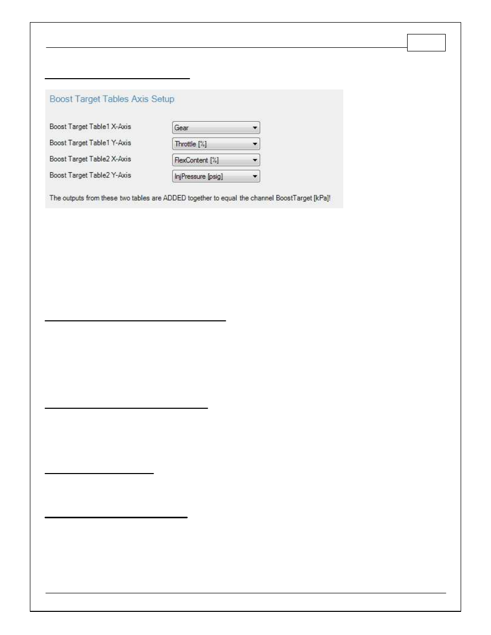
Boost Target Tables Axis Setup
There are two 2D boost target tables in the calibration. They are named:
- BoostTargetTable1 [kPa]
- BoostTargetTable2 [kPa]
These two tables add together so the user can use one table as a primary and the second as a
trim if desired. Both axis inputs are selectable from the drop down lists shown above.
Boost Solenoid Control Frequency [Hz]
Units: Hz
Description: This should be set to the manufacturer specifications. This sets the frequency to
operate the pulse width modulated boost solenoid. If the boost solenoid is excessively noisy and/
or slow to respond, the frequency should be changed. Note: Most boost solenoids make some
noise.
Min value = 0, Max value = 1000
Boost Solenoid Max Duty Cycle [% ]
Units: %
Description: This should be set to the manufacturer specifications. This sets the maximum duty
cycle allowed.
Min value = 0, Max value = 100
Boost Duty Cycle Invert
Units: On/Off
Description: This setting inverts the PID feedback logic.
Boost Integral Gain Low Clamp
Units: Clamp
Description: This keeps the integral gain from winding down and limits its contribution.
Min value = -10, Max value = 10. Note: BoostControlIntClampH must be greater than
BoostControlIntClampL.