AEM 30-71XX Infinity Stand-Alone Programmable Engine Mangement System Full Manual User Manual
Page 365
Wiring, Pinouts and Schematics
359
© 2014 AEM Performance Electronics
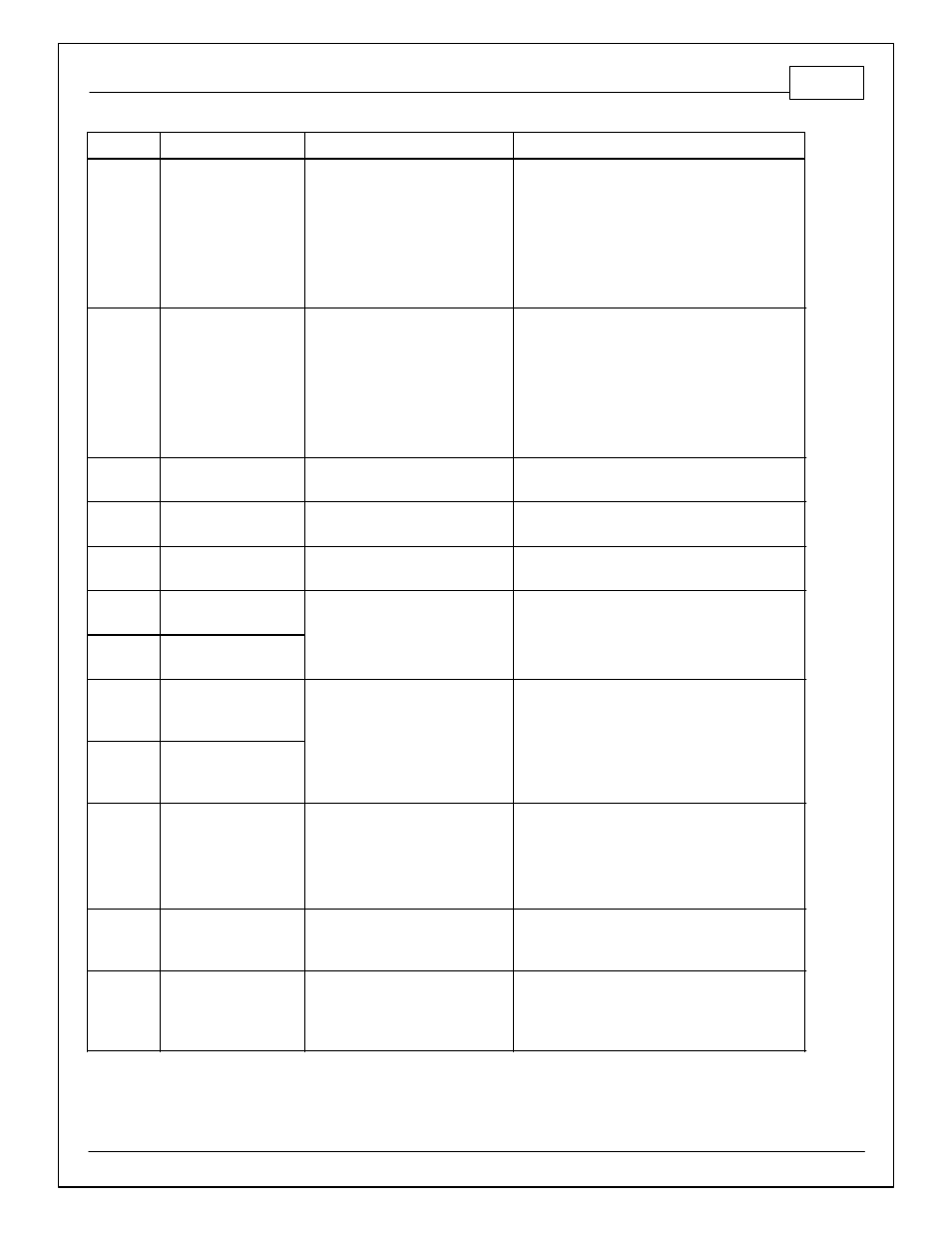
Infinity Pin
Hrdwr Ref.
Hardware Specification
Notes
C2-20
Analog_In_15
12 bit A/D, 100K pullup to 5V
0-5V analog signal. Use +5V Out pins as power
supply and Sensor Ground pins as the low
reference. Do not connect signals referenced to
+12V as this can permanently damage the ECU.
Normally used as Exhaust Back Pressure input.
C2-21
Analog_In_16
12 bit A/D, 100K pullup to 5V
0-5V analog signal. Use +5V Out pins as power
supply and Sensor Ground pins as the low
reference. Do not connect signals referenced to
+12V as this can permanently damage the ECU.
Normally used as DBW1_TPSB input.
C2-22
+5V_Out_2
Regulated, fused +5V supply for
sensor power
Analog sensor power
C2-23
+5V_Out_2
Regulated, fused +5V supply for
sensor power
Analog sensor power
C2-24
+5V_Out_2
Regulated, fused +5V supply for
sensor power
Analog sensor power
C2-25
VR+_In_5
Differential Variable Reluctance
Zero Cross Detection
See Driven Wheel Speed Calibration in the Setup
Wizard Vehicle Speed page.
C2-26
VR-_In_5
C2-27
VR-_In_4
Differential Variable Reluctance
Zero Cross Detection
See Non Driven Wheel Speed Calibration in the
Setup Wizard Vehicle Speed page.
C2-28
V R+_In_4
C2-29
LowsideSwitch_9_Out
Lowside switch, 4A max with
internal flyback diode, 2.2K 12V
pullup. Inductive load should NOT
have full time power.
12V pullup
See Setup Wizard page Tacho for configuration
options.
C2-30
AGND_2_Out
Dedicated analog ground
Analog 0-5V sensor ground
C2-31
AGND_2_Out
Dedicated analog ground
Analog 0-5V sensor ground