Universal pinout, infinity-6/8h – AEM 30-71XX Infinity Stand-Alone Programmable Engine Mangement System Full Manual User Manual
Page 369
Wiring, Pinouts and Schematics
363
© 2014 AEM Performance Electronics
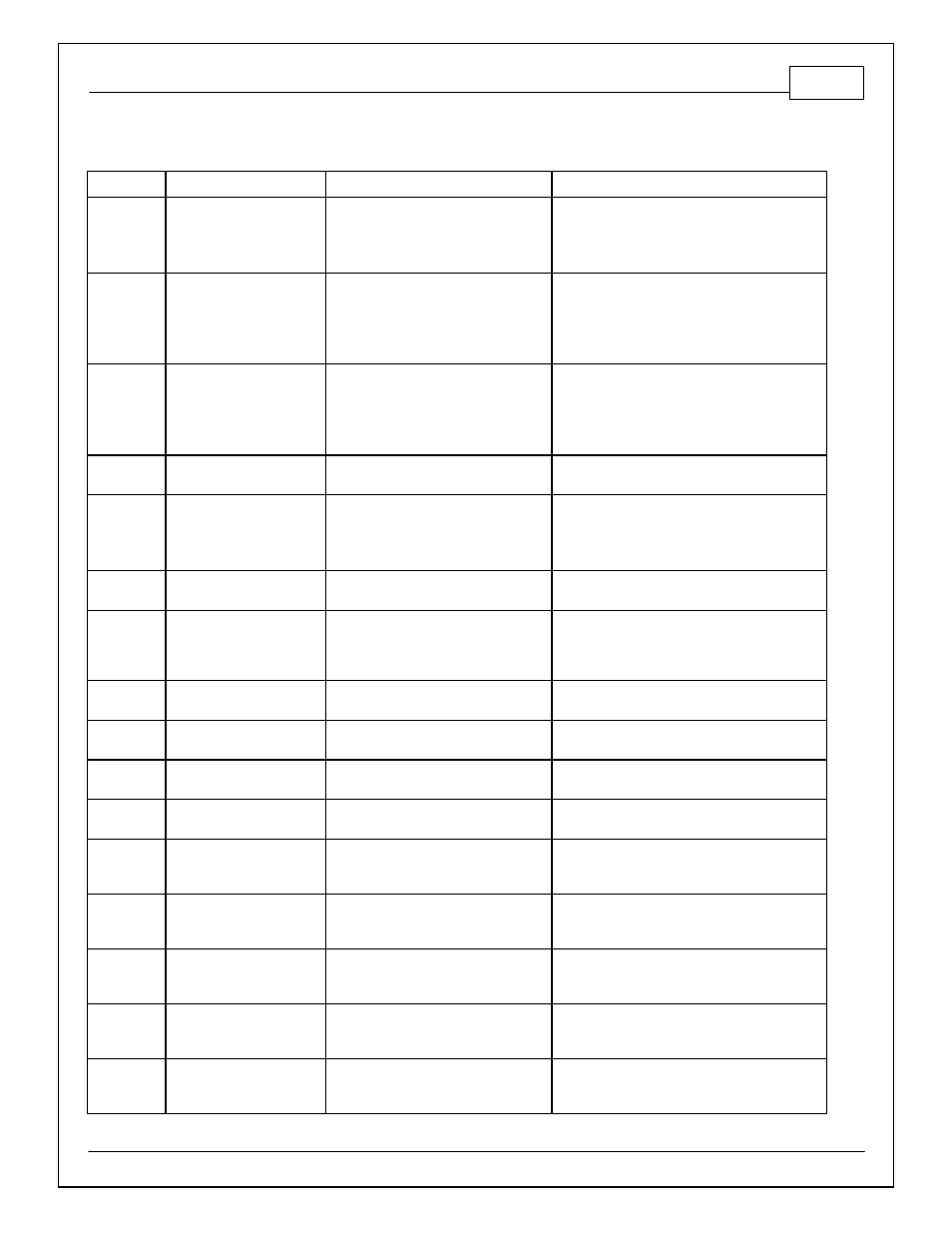
Universal Pinout, Infinity-6/8h
Infinity Pin
Hardware Ref.
Hardware Specification
Notes
C1-1
LowsideSwitch_4_Out
Lowside switch, 1.7A max, NO internal
flyback diode.
12V pullup
See Setup Wizard Pages "User GPOs" for
activation criteria and "LowSide Assignment
Tables" for output assignment
C1-2
LowsideSwitch_5_Out
Lowside switch, 6A max with internal
flyback diode. Inductive load should
NOT have full time power.
12V pullup
See Setup Wizard Page "LowSide Assignment
Tables" for output assignment and 2D table
"LS5_Duty [%]" for activation.
C1-3*
LowsideSwitch_6_Out
(*Infinity-6 Only)
Lowside switch, 6A max with internal
flyback diode. Inductive load should
NOT have full time power.
No pullup
Available on P/N 30-7106 only. See Setup
Wizard Page "LowSide Assignment Tables" for
output assignment and 2D table "LS6_Duty [%]"
for activation.
C1-3**
Injector 7_Out
(**Infinity-8H Only)
For use with high impedance (10-15
ohms) injectors only, 1.7A max.
Available on P/N 30-7108 only
C1-4*
LowsideSwitch_7_Out
(*Infinity-6 Only)
Lowside switch, 6A max, NO internal
flyback diode.
No pullup
Available on P/N 30-7106 only. See Setup
Wizard Page "LowSide Assignment Tables" for
output assignment and 2D table "LS7_Duty [%]"
for activation.
C1-4**
Injector 8_Out
(**Infinity-8H Only)
For use with high impedance (10-15
ohms) injectors only, 1.7A max.
Available on P/N 30-7108 only
C1-5
UEGO 1 Heat_Out
Bosch UEGO controller
Lowside switch for UEGO heater control.
Connect to pin 4 of Bosch UEGO sensor. NOTE
that pin 3 of the Sensor is heater (+) and must be
power by a fused/switched 12V supply.
C1-6
UEGO 1 IA_In
Trim Current signal. Connect to pin 2 of Bosch
UEGO sensor
C1-7
UEGO 1 IP_In
Pumping Current signal. Connect to pin 6 of
Bosch UEGO sensor
C1-8
UEGO 1 UN_In
Nernst Voltage signal. Connect to pin 1 of Bosch
UEGO sensor
C1-9
UEGO 1 VM_In
Virtual Ground signal. Connect to pin 5 of Bosch
UEGO sensor.
C1-10
+12V_R8C_CPU_In
Dedicated power management CPU
Full time battery power. MUST be powered
before the ignition switch input is triggered (See
C1-48).
C1-11
Coil 4_Out
25 mA max source current
0-5V Falling edge fire. DO NOT connect directly
to coil primary. Must use an ignitor OR CDI that
accepts a FALLING edge fire signal.
C1-12
Coil 3_Out
25 mA max source current
0-5V Falling edge fire. DO NOT connect directly
to coil primary. Must use an ignitor OR CDI that
accepts a FALLING edge fire signal.
C1-13
Coil 2_Out
25 mA max source current
0-5V Falling edge fire. DO NOT connect directly
to coil primary. Must use an ignitor OR CDI that
accepts a FALLING edge fire signal.
C1-14
Coil 1_Out
25 mA max source current
0-5V Falling edge fire. DO NOT connect directly
to coil primary. Must use an ignitor OR CDI that
accepts a FALLING edge fire signal.