Network connections, Network connections -13, Figure 3-9 – ADTRAN 1248 User Manual
Page 37: Total access 1248 network connection -13, Table 3-4, T1/e1/modem interface pinout -13
Installation Steps
61179641AL4-5B
3-13
Network Connections
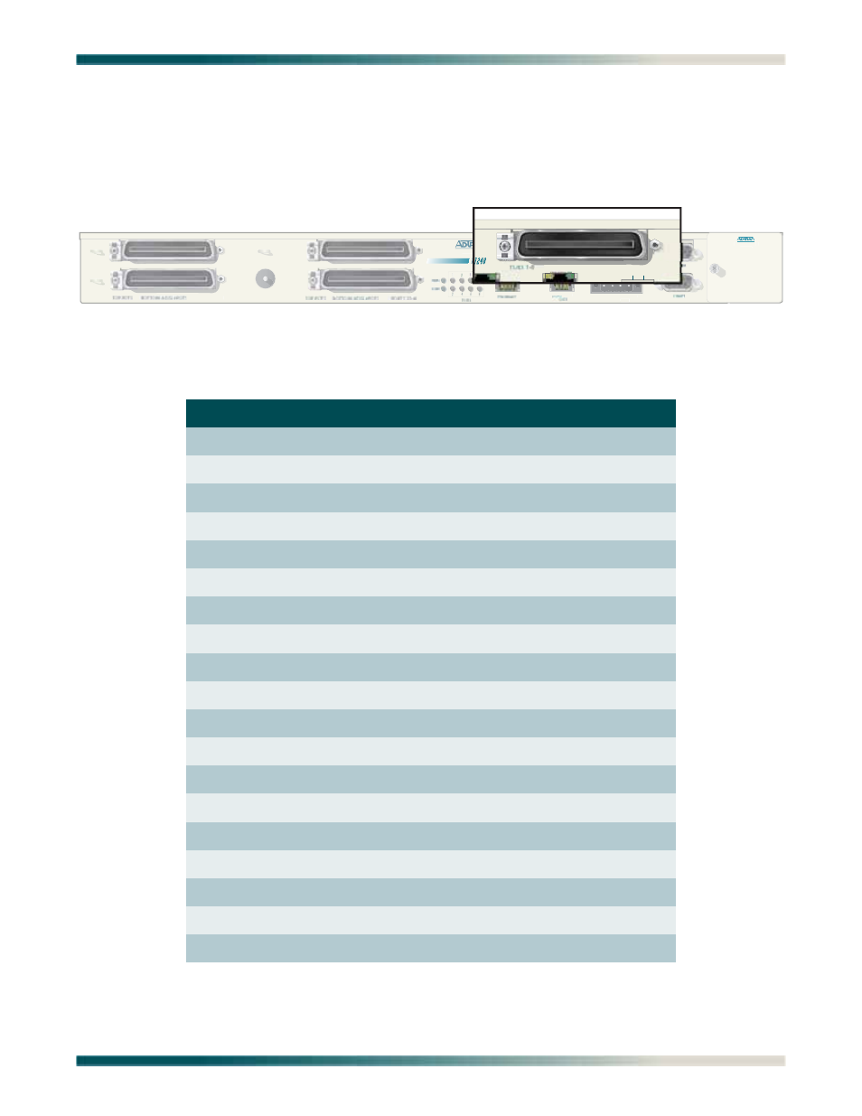
Network connections are accomplished via the 50-pin amphenol connector labeled
T1/E1 1-8
(see
)
. See
for the pinout of the T1/E1 interface and the analog modem.
Figure 3-9. Total Access 1248 Network Connection
Table 3-4. T1/E1/Modem Interface Pinout
Pin Numbers
Description
1, 26
RX Tip/Ring 1
2, 27
TX Tip/Ring 1
3, 28
RX Tip/Ring 2
4, 29
TX Tip/Ring 2
5, 30
RX Tip/Ring 3
6, 31
TX Tip/Ring 3
7, 32
RX Tip/Ring 4
8, 33
TX Tip/Ring 4
9, 34
RX Tip/Ring 5
10, 35
TX Tip/Ring 5
11, 36
RX Tip/Ring 6
12, 37
TX Tip/Ring 6
13, 38
RX Tip/Ring 7
14, 39
TX Tip/Ring 7
15, 40
RX Tip/Ring 8
16, 41
TX Tip/Ring 8
17–24
Unused
42–49
Unused
25, 50
Modem Tip/Ring
FAN MODULE
1179675L1
117964
PORTS 1-24
EXPANSION
-48V .....,5.0A
.
USE COPPER CONDUCTORS ONLY!
A
B
-48V RET
-48V
RET
A
- Express 4110 (205 pages)
- Gigabit Ethernet Multi-Mode Fiber Tributary Module 1184519L1 (2 pages)
- U-BR1TE ISDN 2B1Q (4 pages)
- DSU/CSU (6 pages)
- 3010 (30 pages)
- NetVanta 1024 (2 pages)
- FT1 (10 pages)
- IP Mini-DSLAM (2 pages)
- 6530 (20 pages)
- 6530 (2 pages)
- AHT1U (2 pages)
- DS3 MX (2 pages)
- 600R (264 pages)
- DUAL Nx56/64 1200142L1# (42 pages)
- NetVanta T1/FT1 + DSX-1 (2 pages)
- IQ SERIES 56 (1 page)
- 1200070L2 (187 pages)
- 1200051L2 (165 pages)
- NETVANTA 3120 (2 pages)
- 1200 (2 pages)
- NetVanta Series (2 pages)
- 850 (4 pages)
- ATLAS 800 Series Module QUAD E1 (2 pages)
- Atlas 830 (2 pages)
- TSU LT (2 pages)
- Express L1.5 (2 pages)
- MX2820-48 VDC M13 MUX (2 pages)
- Dial Backup Interface Module 1204006L2 (2 pages)
- 900 Series (2 pages)
- Atlas 550 (1 page)
- Atlas 550 (262 pages)
- NetVanta 5305 (2 pages)
- 1200350L1 (134 pages)
- ATM Mini-DSLAM (2 pages)
- D4-n x 64 DSU DP (4 pages)
- Type 400 (4 pages)
- 1204002L1 (163 pages)
- NetVanta ADSL (2 pages)
- 3000 HTU-C (2 pages)
- 600e (2 pages)
- 1200F (2 pages)
- D4 TRI-C DP (1 page)
- 239 T1 HDSL4 (20 pages)
- 3000 NTU-8 (18 pages)
- 1200130L1 (153 pages)