Festo Кабели и принадлежности User Manual
Page 61
4. Commissioning
4−16
Festo P.BE−SPC200−SMX−1−EN en 0503b
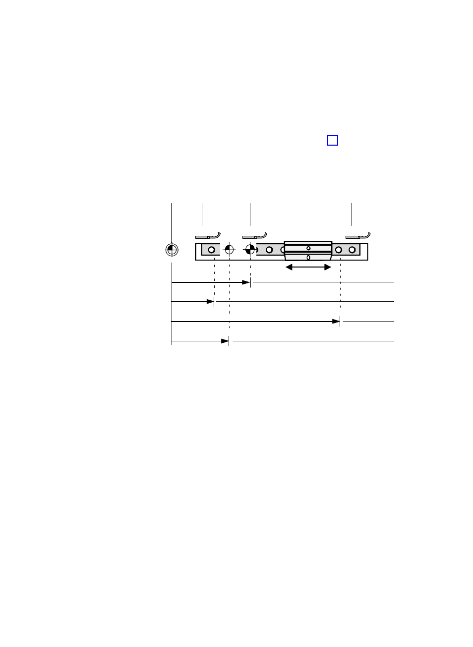
With the following parameters
3
to
6
(see Fig. 4/5) you
can specify the reference points of your positioning system.
The machine zero point is defined by the coordinate of the
reference point. All further positions refer to the thus defined
machine zero point.
1
Machine zero
point
2
Reference and
limit switches
3
Reference
position
4
Lower software
end position
5
Upper software
end position
6
Project zero point
LIM−
REF
LIM+
1
2
3
4
5
6
2
2
Fig. 4/5: Reference points
Project zero point
Point related to the machine zero point. All positions in posiĆ
tion registers and programs refer to the project zero point.
Permitted: 0.0 ... 10.0000 [mm]
Lower software end
position
Defined end position on the side of the machine zero point
which is monitored by the SPC200 and which must not be
overrun. The lower software end position refers to the maĆ
chine zero point and represents the lower limit of the posiĆ
tioning range.
Permitted: 0.0 ... 10.0000 [mm]