5 wiring, Figure 11 – HID EntryProx Installation Guide User Manual
Page 23
EntryProx™ User Guide
Part No. 4045-905, Rev C.2
5 WIRING
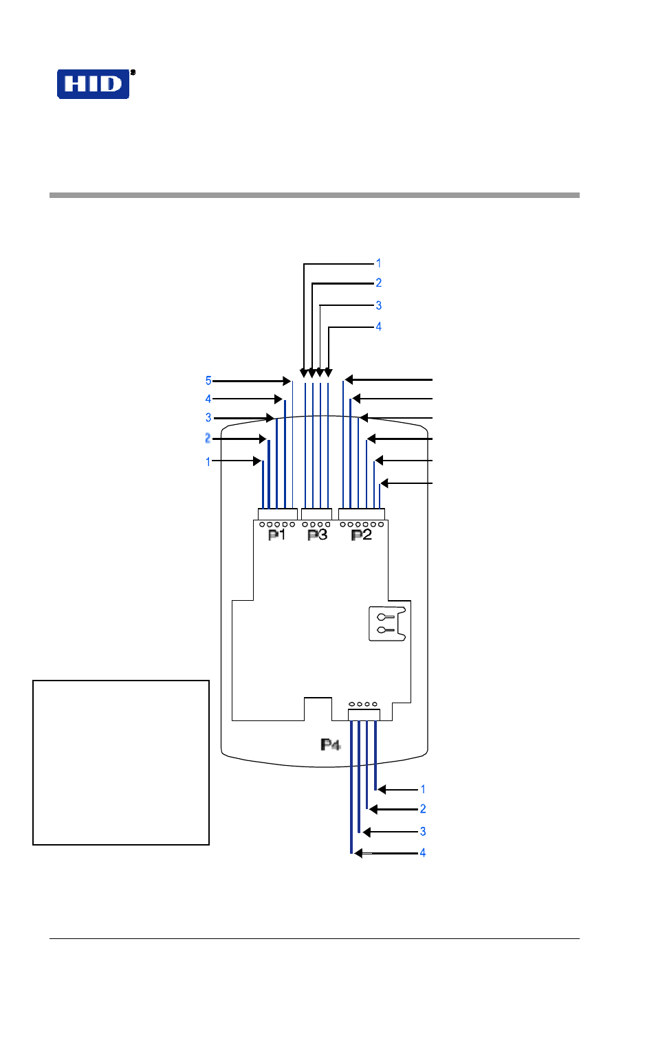
Figure 11 illustrates the location and description of the four pin connectors on
the main circuit board and its use. Connector P5 is not used.
Blue – Not Used
Brown – Wiegand LED Control
White – Wiegand Data 1
Green – Wiegand Data 0
Red – Power +12 VDC
Green – Aux Relay NO
Black – Ground
Gray – Aux Relay NC
Blue – Main Relay COM
Blue – Aux Relay COM
Green – Main Relay NO
Brown – Rex Loop
Gray – Main Relay NC
Orange – Door Loop
White – Loop Common*
*Note: Rex Loop
requires NO switch;
Door Loop requires
NC switch. Connect
commons from both
loops to Loop
Common input P2, Pin
6, White.
Red – LED (Red +)
Black – LED (Green +)
Antenna +
Antenna -
Figure 11 Pin Locator Diagram
February 7, 2007
Page 23 of 58
© 2007 HID Global Corporation. All rights reserved.
- bioCLASS Installation Guide (12 pages)
- Crescendo Integration (54 pages)
- EDGE EVO EDM-M Door Module Installation Guide (4 pages)
- EDGE EVO EDWM-M Door-Wiegand Module Installation Guide (4 pages)
- EDGE EVO EH400 Hi-O Controller Installation Guide (12 pages)
- EDGE EVO Solo ESH400 Hi-O Controller Installation Guide (12 pages)
- EDGE EVO EH400-K Standard Controller Installation Guide (12 pages)
- EDGE EVO Solo ESHR40 Hi-O Controller/Reader Installation Guide (12 pages)
- EDGE EVO EIM-M Hi-O Input Module Installation Guide (2 pages)
- EDGE EVO EIM-M Input Module Installation Guide (2 pages)
- EDGE EVO ELM Hi-O Lock Module Installation Guide (2 pages)
- EDGE EVO ELM Lock Module Installation Guide (2 pages)
- EDGE EVO EVM Hi-O Voltage Module Installation Guide (2 pages)
- EDGE EVO EVM Voltage Module Installation Guide (2 pages)
- EDGE EVO Hi-O Interface Door Module Installation Guide (4 pages)
- EDGE EVO Solo ESH400-K Networked Controller Installation Guide (10 pages)
- EDGE EWM-M Hi-O Wiegand module Installation Guide (4 pages)
- EDGE Plus Installation Guide (2 pages)
- MIFARE Reader Installation Guide (6 pages)
- Hi-O iCLASS Installation Guide (49 pages)
- iCLASS Keypad Installation Guide (12 pages)
- iCLASS R Installation Guide (12 pages)
- iCLASS RK Series Rev C Installation Guide (12 pages)
- iCLASS SE Installation Guide (10 pages)
- iCLASS SE/ multiClass SE Installation Guide (10 pages)
- Magnetic Stripe / Prox Reader 230 and 240 Installation Guide (2 pages)
- Magnetic Stripe Reader 644 Installation Guide (2 pages)
- Magnetic Stripe Reader 740 Installation Guide (2 pages)
- Magnetic Stripe Reader 780 Installation Guide (2 pages)
- MaxiProx Installation Guide (19 pages)
- multiCLASS / Magnetic Stripe Installation Guide (12 pages)
- multiCLASS / Magnetic Stripe with Keypad Installation Guide (10 pages)
- multiCLASS RP Series Hi-O Installation Guide (6 pages)
- pivClass Installation Guide (8 pages)
- Prox Programmer Installation Guide (21 pages)
- ProxPass Installation Guide (3 pages)
- ProxPoint Installation Guide (3 pages)
- ProxPoint Plus Installation Guide (2 pages)
- ProxPro II Installation Guide (2 pages)
- ProxPro Installation Guide (14 pages)
- Serial ProxPro Reader Installation Guide (10 pages)
- SmartID Mounting Plate Installation Guide (2 pages)
- SmartID Spacer Installation Guide (2 pages)
- VertX EVO V1000 Installation Guide (19 pages)