HID EDGE EVO ELM Hi-O Lock Module Installation Guide User Manual
Edge evo, Lock module, 0 x 1
Lock Module (Base P/N 82301)
This Hi-O interface module is wired to interface the EDGE EVO device (Controller/Reader & Module
or Networked Controller) with
electronic door components. The 0 x 1 module provides outputs to an electronic locking device.
Specifications
CONDITIONS
VOLTAGE DC
(VDC)
CURRENT
(Amp)
OPERATING
TEMPERTURE
CABLE LENGTH
UL REFERENCE
NUMBER
Input
DC Input (NSC)
10.8 to 24VDC
0.04Amp
32° - 122°F
(0° - 50° C)
Lock Control Circuit
100 ft (30 m)
= 22 AWG ● 0.65mm ● 0.33mm
2
200 ft (60 m)
= 18 AWG ● 1.02mm ● 0.82mm
2
Hi-O CAN Bus Total Length 100 ft (30 m) -
22 AWG ● 0.65mm ● 0.33mm
2
Maximum between drops 30 ft (10 m)
22 AWG ● 0.65mm ● 0.33mm
2
ELMAxNN
X = K for Black
G for Gray
DC Input (MAX)
10.8 to 24VDC
1.2Amp
Ouput
DC Output
Jumpers Set to
Regulated or Unregulated (Wet) (MAX)
10 to 24VDC
.30 to 1.0Amp
NSC = Normal Standby Condition
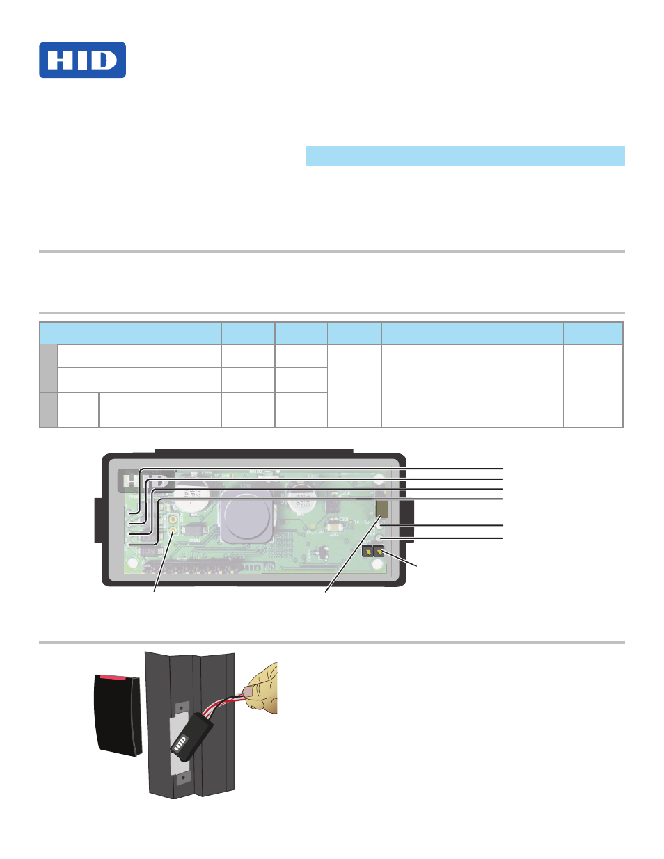
0 x 1
Termination
Jumper
CAN V+
GND
CAN_H
CAN_L
Red
Black
White
Brown
DC Output
GND
White / Red
White / Black
See Output Power
Selection table
Door Strike
Hi-O Group Select Jumper
Short = Group 1, Open = Group 2
Outside Door
Inside Door
( )
CANbus
1
3
P103
Mounting
EDGE EVO
®
Lock Module
Model: ELM
I
nstallatIon
G
uIde
82301-901, Rev B.0
September 2011
© 2009 - 2011 HID Global Corporation. All rights reserved.
15370 Barranca Parkway
Irvine, CA 92618-2215
USA
Install the EDGE EVO Lock Module within a UL
Listed single-gang electrical box or optionally
within a hallow metal door frame (shown).