Allied Telesis AT-S25 User Manual
Page 99
AT-S25 Version 1.4 User’s Guide
99
3. Select Virtual LAN definitions.
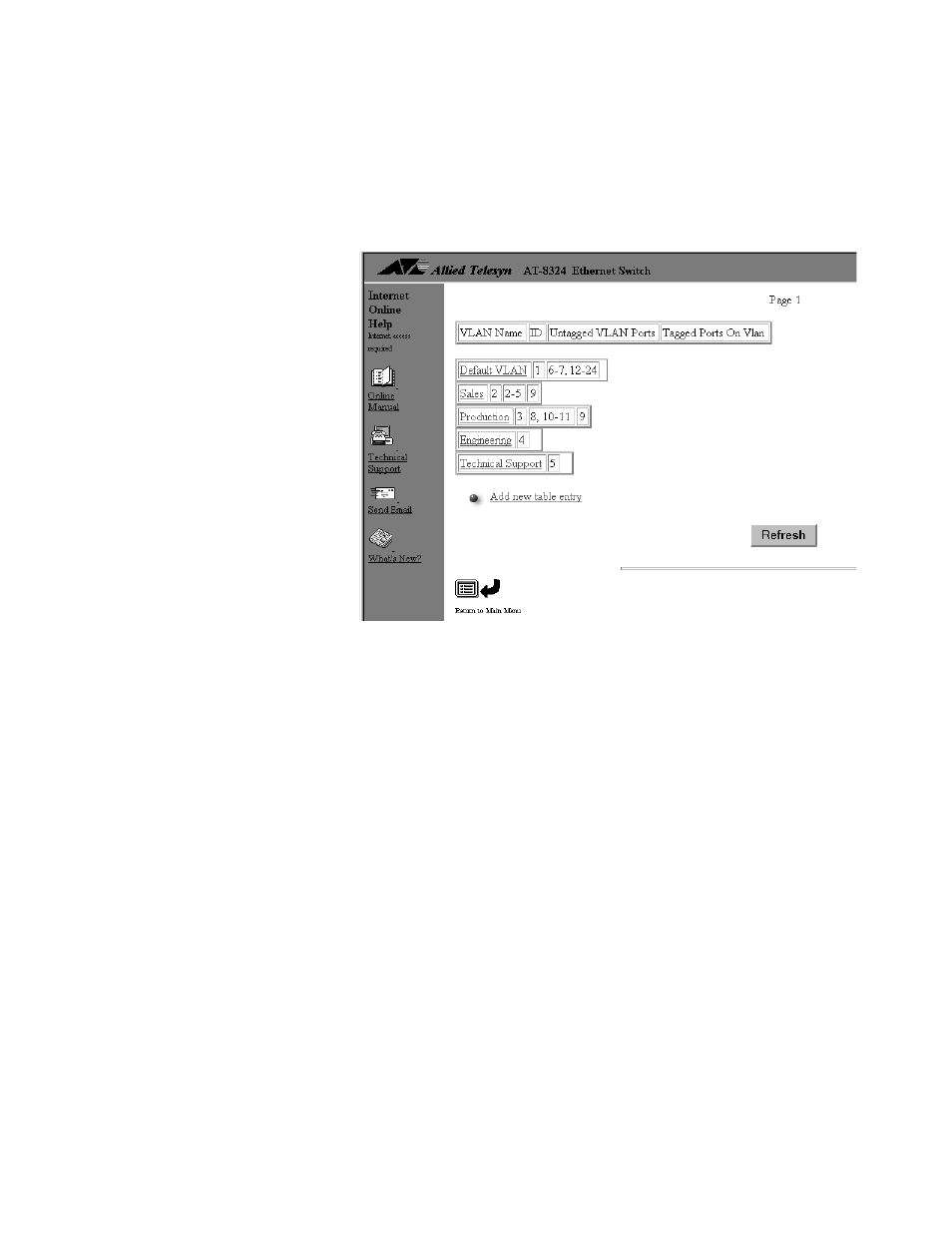
The program displays the VLANs window. This window lists the
VLANs currently existing on the stack. The window provides the
name of each VLAN along with the ports on the currently selected
switch that are members of the VLAN. Figure 49 is an example of
the window.
Figure 49 VLANs Window
The example shows that there are five VLANs on the stack: Default
VLAN, Sales, Production, Engineering, and Technical Support. The
numbers following each VLAN indicate the VID number of the
VLAN and the untagged and tagged ports that belong to the
VLAN. For example, the Production VLAN has the VID number of
3. Ports 8, 10, and 11 on the currently selected switch have been
assigned to this VLAN as untagged ports and port 9 on the switch
has been designated as a tagged port.
The example VLANs window also includes the two VLANs
Engineering and Technical Support. The currently selected switch
does not have ports that are members of these VLANs, which is
why there are no ports listed after the VLAN names.
4. Select Add new table entry.
The VLAN Configuration window shown in Figure 50 is displayed.
You use this window to specify the parameters for the new VLAN,
such as its name and the ports on the currently selected switch
that will be members of the VLAN.