Allied Telesis AT-S25 User Manual
Page 151
AT-S25 Version 1.4 User’s Guide
151
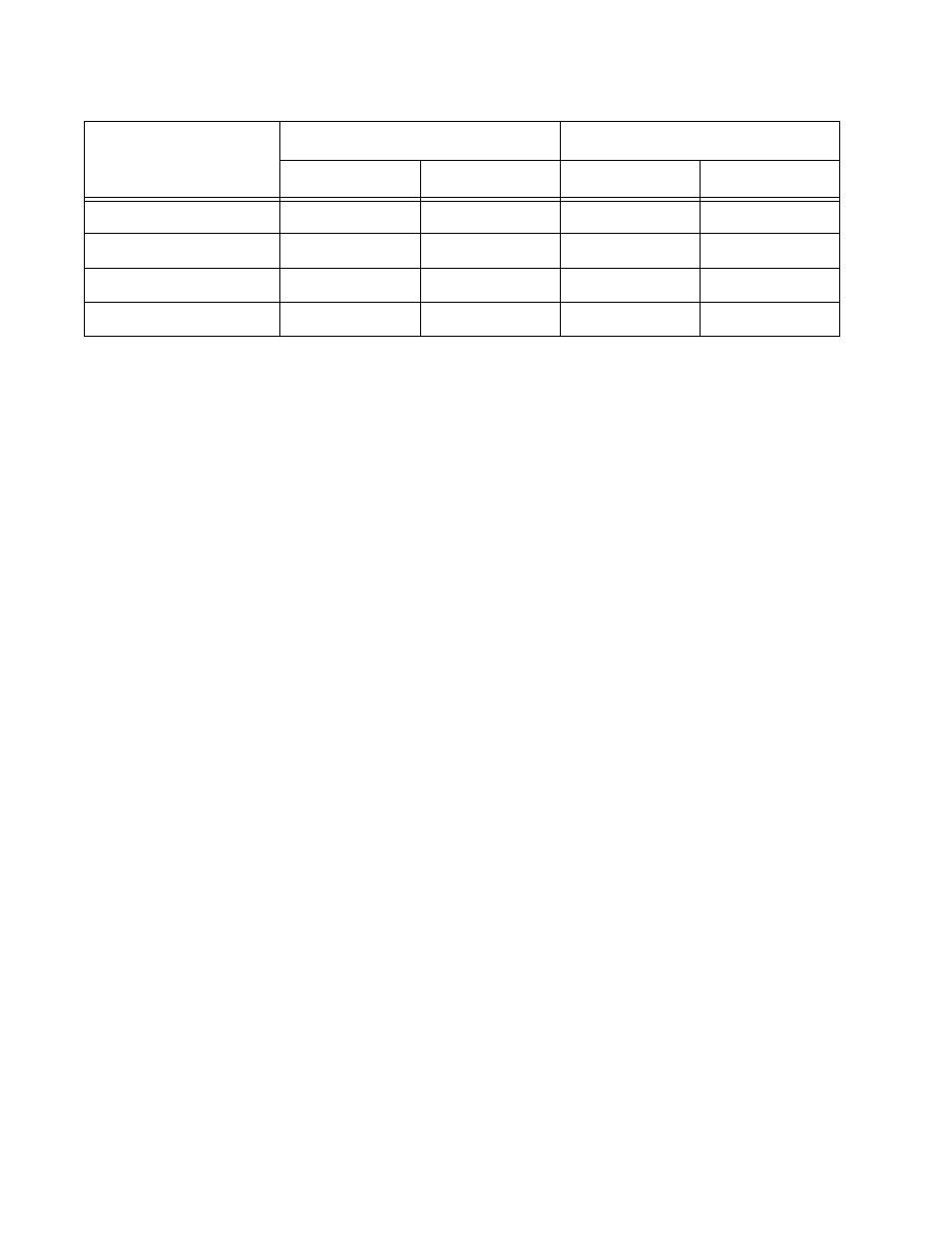
The port assignments for the VLANs are as follows:
This configuration is similar to the port-based VLAN example earlier in
this appendix, but untagged ports have replaced several connections.
The changes are noted below:
❑ Uplink to the AT-8224XL switch - In the earlier port-based VLAN
example, each VLAN in the AT-8300 stack had a dedicated
connection to its corresponding VLAN in the AT-8224XL Switch.
These connections have been replaced with one connection. Port
10 on the AT-8324 slave switch has been made a tagged member
of both VLANs, as has port 9 on the AT-8224XL switch. The
connection between the ports now carries traffic for both VLANs.
However, frame traffic is restricted to its respective VLAN member
ports.
❑ Uplink to an IEEE 802.1Q-compliant server - Port 16 on the AT-
8324 slave switch has been connected to an IEEE 802.1Q-
compliant server, meaning the device is capable of handling
tagged frames. By designating it as a tagged port of both the Sales
and Production VLANs, end-nodes from either VLAN can access
the resource without having to pass through a router.
❑ Uplink to an IEEE 802.1Q-compliant router - Port 11 on the AT-
8324 master switch has been connected to a router and has be
made a tagged member of both VLANs. Access to the WAN is now
possible for both VLANs over the one connection.
Sales VLAN (VID 2)
Production VLAN (VID 3)
Untagged Ports
Tagged Ports
Untagged Ports
Tagged Ports
AT-8300 Series Stack
AT-8324 Switch (Master)
1 to 6 (PVID 2)
11
19 - 24 (PVID 3)
11
AT-8324 Switch (Slave)
1 - 4 (PVID 2)
10, 16
22 - 24 (PVID 3)
10, 16
AT-8224XL Switch
1 - 4 (PVID 2)
9
21 - 24 (PVID 3)
9