Ag Leader ParaDyme Operation Guide User Manual
Page 19
17
- Combine/Swather - Front Axle
Note:
Be sure to select the appropriate offset for your configuration by pressing the Fore or Aft
button.
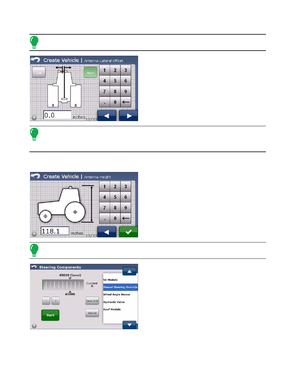
10. Enter the Antenna Lateral Offset value using the
numeric keypad and then select the Left Arrow or Right
Arrow button as applicable to your installation. When
finished, press the Right Arrow button. The Antenna
Height screen appears.
Note:
The Antenna Lateral Offset value is tested and adjusted (if necessary) after vehicle creation
and calibration is complete. See
“Adjust Lateral Offset” on page 23
. The Left Arrow and Right Arrow
buttons define the antenna position (center of the Roof Module) relative to the vehicle’s center line
when viewed from the rear.
Be sure to select the appropriate offset for your configuration by pressing the Left Arrow or Right Arrow
button.
11. Enter the Antenna Height value using the numeric
keypad and then press the check mark button. The
Manual Steering Override screen appears.
Note:
Antenna height is measured from the antenna ground plane bottom to the ground surface.
12. You are now in the Manual Steering Override
kickout limit setting procedure. See
Override (Autosteering Kick-out Limit Adjustment)” on
page 26
for details about the procedure.
13. When the Manual Steering Override calibration is
complete, the Setup Wizard starts the Auto Calibrate
procedure. See