Technical data, 3 swirl compensation – KROHNE ALTOSONIC V12 EN User Manual
Page 99
TECHNICAL DATA
9
99
ALTOSONIC V12
www.krohne.com
04/2013 - 4002643502 - MA ALTOSONIC V12 R02 en
The velocity of the gas is derived from formula (1) and (2) as:
An important feature of this method is that the calculated gas velocity does not depend on the
speed of sound in the gas or gas properties in general. The gas velocity as calculated is only a
function of the measured transit times t
AB
and t
BA
; the length of the chord and the angle of
intersection of the measuring chord are supposed to be known from the design of the flowmeter.
As a “bonus” the speed of sound in the gas can be derived from formula (1) and (2) as :
This gives a measured speed of sound value, a valuable tool for diagnostic purposes, as it can be
compared with data from other sources.
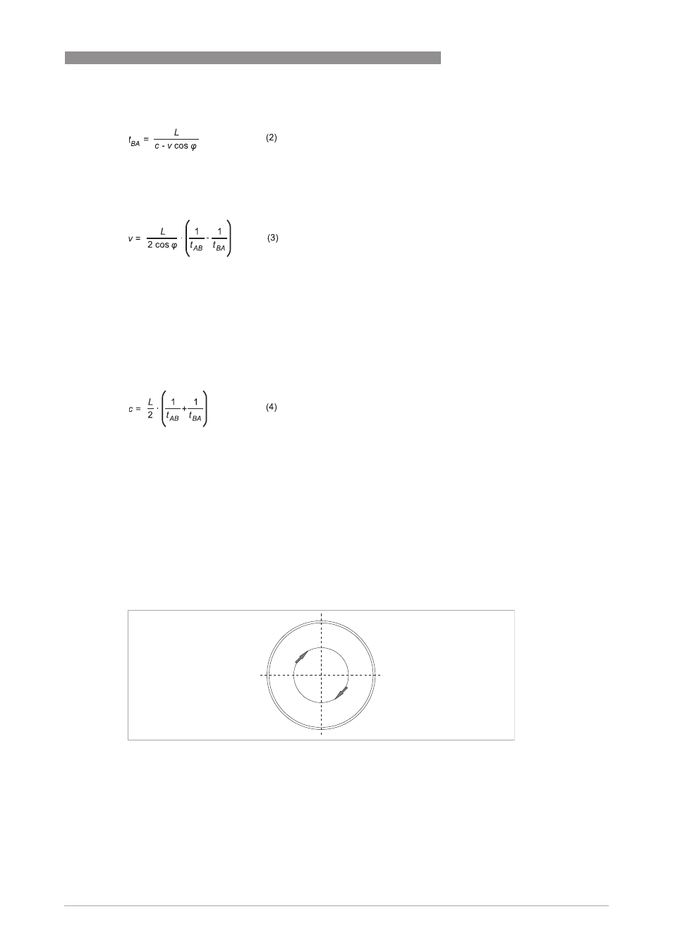
9.3 Swirl compensation
At specific spots in the pipe, the local gas velocity vector may not be exactly parallel to the pipe
axis. This effect can be the result of a flow velocity pattern called swirl. This is a frequently
occurring velocity pattern where the gas mass in the pipe rotates as it flows. As an example, the
flow velocity pattern after a double out-of-plane bend is shown below.
Another velocity pattern that frequently occurs, especially downstream of a single elbow or bend
in the pipeline, is shown in the picture below. There, just after the bend, the gas mass splits in
two contra rotating vortices.
Figure 9-2: Swirl pattern after a double out-of-plane bend