Electrical connections – KROHNE ALTOSONIC V12 EN User Manual
Page 26
4
ELECTRICAL CONNECTIONS
26
ALTOSONIC V12
www.krohne.com
04/2013 - 4002643502 - MA ALTOSONIC V12 R02 en
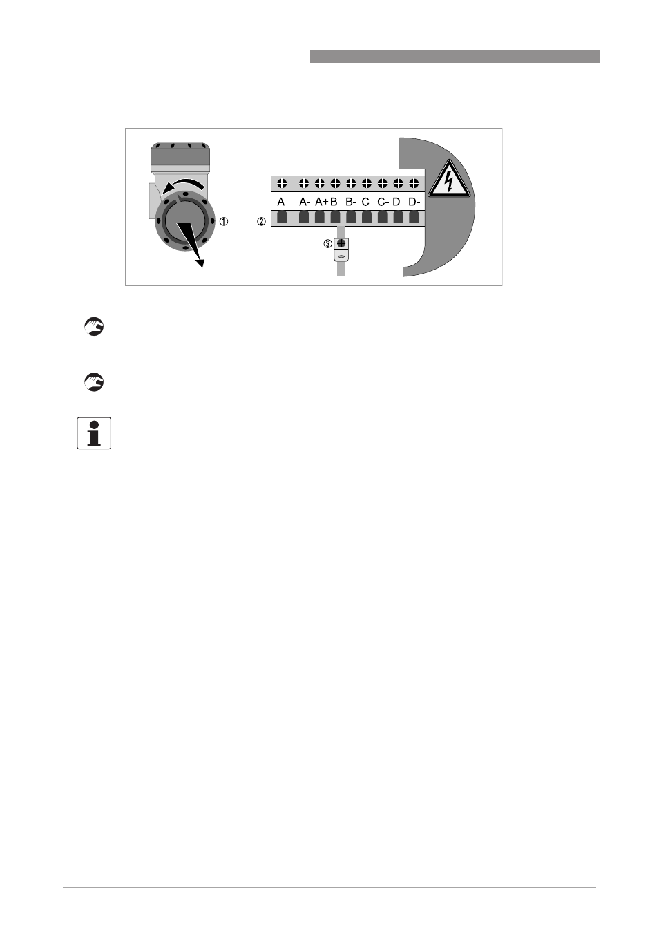
1 Open the housing cover.
2 Push the prepared cable through the cable entry and connect the necessary conductors.
3 Connect the shield if necessary.
• Close the cover of the terminal compartment.
• Close the housing cover.
4.3.1 Pulse and frequency output
Default the first digital I/O connection is set as a pulse/frequency output, having a frequency
proportional to the volume flow rate (actual volume: under process conditions). It is possible to
assign another variable to control this output (defined by means of parameter settings).
4.3.2 Status outputs
Default the next three digital I/O connections are defined as status outputs (Data not valid, Fail
unreliable and Reverse flow). However the function of these outputs can be programmed to
various alarms or status signals. One of the status outputs may be programmed to a second
pulse output, having the same frequency as the first pulse output, however the phase difference
can be set to either 0, 90, 180 or 270 degrees.
Figure 4-3: Terminal compartment for inputs and outputs in field housing
INFORMATION!
Each time a housing cover is opened, the thread should be cleaned and greased. Use only resin-
free and acid-free grease.
Ensure that the housing gasket is properly fitted, clean and undamaged.