Installation, 5 control valves – KROHNE ALTOSONIC V12 EN User Manual
Page 21
INSTALLATION
3
21
ALTOSONIC V12
www.krohne.com
04/2013 - 4002643502 - MA ALTOSONIC V12 R02 en
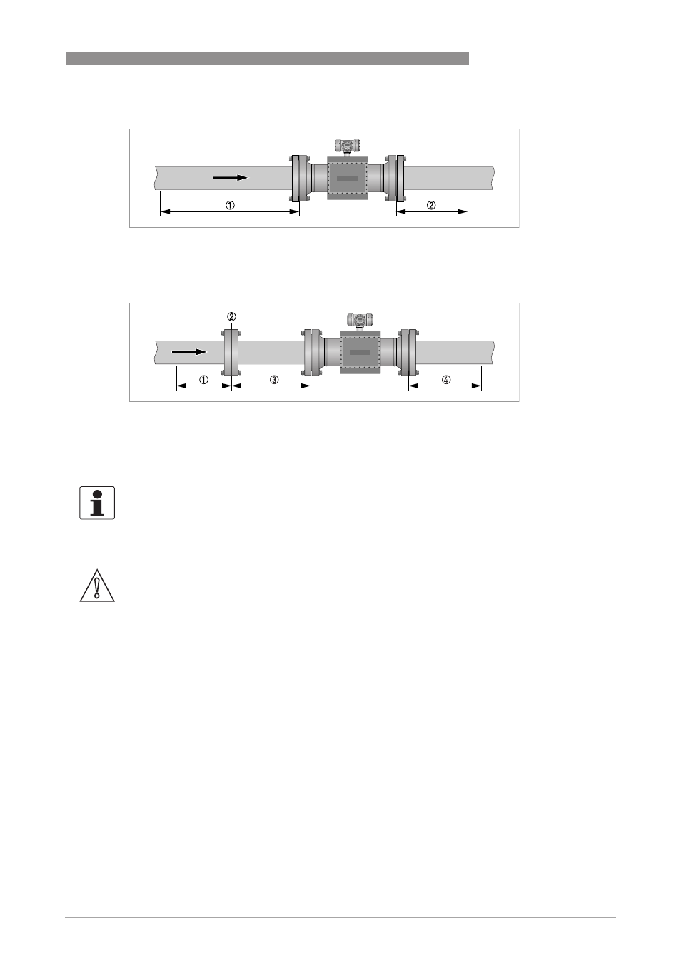
3.5.5 Control valves
Without flow conditioner (AGA9, ISO 17089 and OIML R137 class 1)
Figure 3-3: Reguired straight lengths for inlet and outlet
1 Inlet section: 5 DN
2 Outlet section: 3 DN
With flow conditioner
Figure 3-4: Reguired straight lengths for inlet and outlet
1 Inlet section before flow conditioner: 2 DN
2 Flow conditioner (perforated plate)
3 Inlet section after flow conditioner: 3 DN
4 Outlet section: 3 DN
INFORMATION!
Contact KROHNE for recommendations on bi-directional use.
CAUTION!
Under circumstances ultrasonic gas flowmeters can suffer from interference from noise
generated by pressure control valves (PCV). In case the frequency spectrum of the PCV-noise
extends in the range of the operation frequency of the ultrasonic transducers and the strength of
the noise results in a signal to noise ratio smaller than the critical value, the ultrasonic
flowmeter will not be able to operate. Consult the manufacturer for advice in case a PCV with
high pressure cut will be operated close to the ultrasonic flowmeter.