Service – KROHNE ALTOSONIC V12 EN User Manual
Page 90
8
SERVICE
90
ALTOSONIC V12
www.krohne.com
04/2013 - 4002643502 - MA ALTOSONIC V12 R02 en
Step 7: Extracting the transducer
• Turn the hand wheel a few (one or two) turns clockwise until resistance is ensed as a result of
the hexagon at the end of the shaft becoming engaged with the adapter.
• Use the ruler to measure the position of the shaft relative to the tube (the distance between
the inner side of the hand wheel and the adjusting disk).
• Memorize and note this value as "Reference".
• Pull the knob of the locking device to unlock it and rotate it 90 degrees to fix it in that position.
• Turn the adjusting disk counter clockwise to move the main axis further into the retraction
tool.
• Continue turning until steeply increasing resistance is sensed, preventing it to move any
further.
• Measure the position of the shaft relative to the tube.
• Check that the shaft has moved at least 33 mm further compared to the measurement at the
previous item ("Reference").
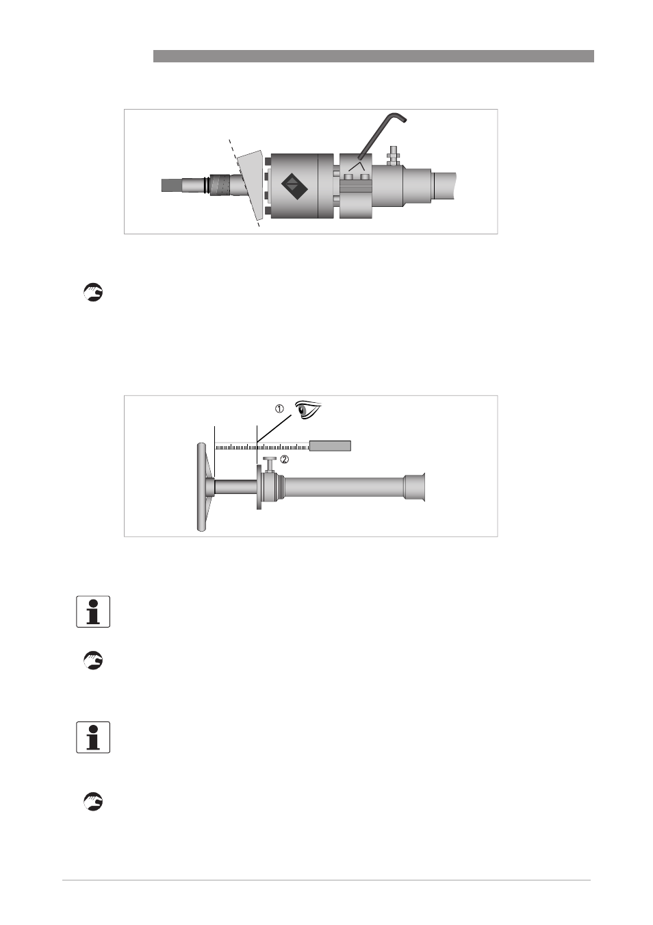
Figure 8-28: Clamping device
Figure 8-29: Measure shaft length
1 Read the distance.
2 Knob of the locking device.
INFORMATION!
The adjusting disk is now free to rotate.
INFORMATION!
This should happen after approximately 18 turns. The hexagon at the end of the main shaft is
completely inserted in the transducer adapter and pushed back against the end of the shaft
(against the spring load).