Modbus protocol description and set-up, 8 modbus register mapping – KROHNE ALTOSONIC V12 EN User Manual
Page 127
MODBUS PROTOCOL DESCRIPTION AND SET-UP
10
127
ALTOSONIC V12
www.krohne.com
04/2013 - 4002643502 - MA ALTOSONIC V12 R02 en
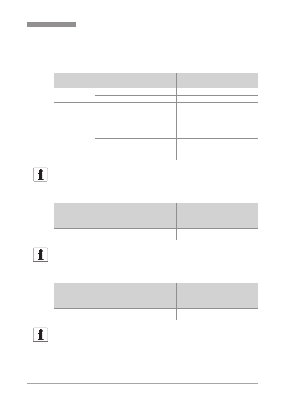
10.8 Modbus register mapping
Registers are mapped to specific address ranges according to both data and register type:
10.8.1 Input Registers (read-only): Integer (16-bit); address range 3000-3499
10.8.2 Holding Registers (read/write): Integer (16-bit); address range 3500-3999
Data type
Register type
Read
command(s)
Write
command(s)
Address range
Integer
(16 bit)
Input register
4
n.a.
3000..3499
Holding register
3
6, 16
3500..3999
Long integer
(32 bit)
Input register
4
n.a.
5000..5499
Holding register
3
6, 16
5500..5999
Double
(64 bit)
Input register
4
n.a.
6000..6499
Holding register
3
6, 16
6500..6999
Float
(32 bit)
Input register
4
n.a.
7000..7499
Holding register
3
6, 16
7500..7999
Long long
(64 bit)
Input register
4
n.a.
8000..8499
Holding register
3
6, 16
8500..8999
INFORMATION!
The relative addresses listed in the tables below are addresses relative to the starting address of
the designated register group.
Relative
address
Absolute address
Name
Parameter /
Variable
(short
description)
non-Modicon
Modicon-comp.
0
3000
3000-3001
(2 regs)
TestRegister
uint 16
Test Register
INFORMATION!
Register reserved for testing communications and protocol handling with this type of register,
without affecting the operation of the flowmeter.
Relative
address
Absolute address
Name
Parameter /
Variable
(short
description)
non-Modicon
Modicon-comp.
0
3500
3500-3501
(2 regs)
TestRegister
uint 16
Test Register
INFORMATION!
Register reserved for testing communications and protocol handling with this type of register,
without affecting the operation of the flowmeter.