Installation – KROHNE ALTOSONIC V12 EN User Manual
Page 20
3
INSTALLATION
20
ALTOSONIC V12
www.krohne.com
04/2013 - 4002643502 - MA ALTOSONIC V12 R02 en
In order to install the gas flowmeter, the pipeline must have a slot of such length that the meter
including the gaskets fits nicely in the slot. It should not be necessary to use excessive force to
tighten the bolts in order to close the gaps on either side of the meter.
Nor should the slot be too small, implying the slot has to be widened by applying brute force to fit
the meter and gaskets in the slot.
For tightening the bolts of the flanges, apply a lubricant as required, in accordance with the
materials as used and applicable standards.
Tighten the bolts of the flanges with a torque according to the standards applicable to the
flanges and materials used.
3.5.2 Pipe diameters and lengths
Make sure that the inner diameter of upstream and downstream pipes matches the specified
connection diameter of the ultrasonic flowmeter within 1%. Contact KROHNE if the iner diameter
deviates more than 1%.
3.5.3 Flow conditioners
Although the flowmeter is a highly accurate device, an additional flow conditioner can be
installed upstream of the flowmeter in order to minimize measuring uncertainty, in particular
when a strongly distorted flow velocity profile has to be expected, or when the available space for
a metering run is critical. If a flow conditioner is used the total inlet length may be reduced to
only 5 DN: having 2 DN upstream of the flow conditioner and 3 DN in between the flow
conditioner and the flowmeter.
3.5.4 Inlet and outlet for uni-directional use
INFORMATION!
•
Preferred model is the
“
perforated plate
”
type. A
“
pipe bundle
”
type of flow conditioner is not
recommended.
•
When a flow conditioner is included in the metering run, it is strongly advised to use the same
flow conditioner and inlet pipe configuration during a flow (wet) calibration (see e.g. ISO17089
or AGA-9 for detailed requirements).
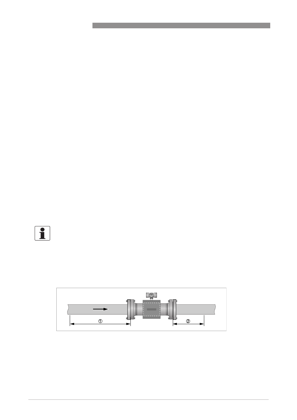
Without flow conditioner (OIML R137 class 0.5)
Figure 3-2: Reguired straight lengths for inlet and outlet
1 Inlet section: 10 DN
2 Outlet section: 3 DN