Modbus protocol description and set-up, 1 integer (16 bit), transmit sequence, 2 long integer (32 bit), transmit sequence – KROHNE ALTOSONIC V12 EN User Manual
Page 122
10
MODBUS PROTOCOL DESCRIPTION AND SET-UP
122
ALTOSONIC V12
www.krohne.com
04/2013 - 4002643502 - MA ALTOSONIC V12 R02 en
Note that in Modicon compatible mode
Modicon compatible mode
Modicon compatible mode
Modicon compatible mode each data type larger than 16 bits should be addressed as
an appropriate number of 16-bit registers. For instance the first float is located at address
7000/7001; the next float is located at address 7002/7003.
A double would be accessed by four 16-bit registers, so the first double 6000/6001/6002/6003
and the next double 6004/6005/6006/6007.
The data in the chapter 8, “MODBUS REGISTER MAPPING”, is printed both as it should be
addressed in Modicon compatible and as well as in not-Modicon compatible mode
not-Modicon compatible mode
not-Modicon compatible mode
not-Modicon compatible mode.
10.6.1 Integer (16 bit), Transmit sequence
Integers are transmitted and stored with the most significant part first.
Example
Integer value 1790 decimal (6FE hexadecimal) is transmitted as:
10.6.2 Long integer (32 bit), Transmit Sequence
Example
Long integer value 305419896 (12345678 hexadecimal).
Long integers could be transmitted in two possible ways. The transmit order in both modes:
Example long integers
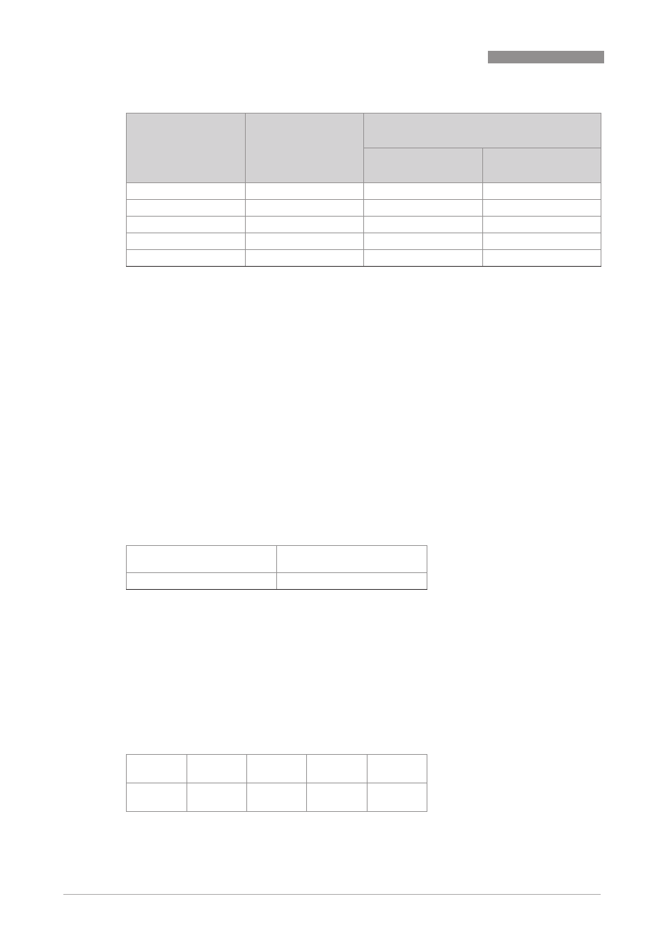
Data Type
Address range
Numbers of registers to request for each data
type
Modicon
compatible
Not Modicon
compatible
Integer (16 bit)
3000...3999
1
1
Long integer (32 bit)
5000...5999
2
1
Double (64 bit)
6000...6999
4
1
Float (32 bit)
7000...7999
2
1
Long long (64 bit)
8000...8999
4
1
Table 10-11: Number of registers
First transmitted byte in data
field
Second transmitted byte in data
field
06
FE
Table 10-12: Example integer (16 bit)
Normal
mode
(1)
12
h
(2)
34
h
(3)
56
h
(4)
78
h
Reversed
mode
(3)
56
h
(4)
78
h
(1)
12
h
(2)
34
h