Service, 2 procedure to remove a transducer – KROHNE ALTOSONIC V12 EN User Manual
Page 82
8
SERVICE
82
ALTOSONIC V12
www.krohne.com
04/2013 - 4002643502 - MA ALTOSONIC V12 R02 en
8.5.2 Procedure to remove a transducer
Step 1: Locate the suspect transducer
• Locate the position of the suspect transducer on the meter body.
• Switch off the electric power supply to the gas flowmeter.
• Remove the cover as necessary to gain access to the suspect transducer and the signal cable
that connect to the transducer.
In case of a warning, a problem or a failure, a technician using the diagnostic tool that is
available for the ultrasonic gas flowmeter, will be able to identify the number of the acoustic
path that most likely causes the problem.
The transducers are identified with codes as: 1U, 1D, 2U ... 6D. The number refers to the acoustic
path number. A "U" refers to the upstream transducer and a "D" refers to the downstream
transducer of an acoustic path.
For an ALTOSONIC V12 six transducers (belonging to three acoustic paths) are located on one
side (front) of the flowmeter. The codes and locations of these transducers are indicated in the
figure below.
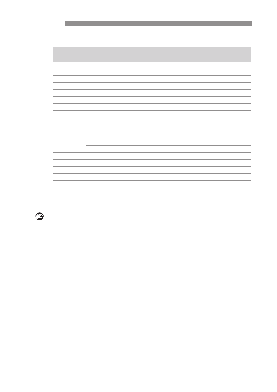
Number in
picture
Description
1
Hand wheel at upper end of the main shaft
2
Adjusting disk to position the shaft
3
Locking device
4
Main shaft
5
Tube
6
Pressure relief valve
7
Clamping device
8
Handle to operate the ball valve
9
Ball valve
10
Intermediate flange
Only to be used for flowmeters with welded transducers
11
Wedge shape adapter
Only to be used for flowmeters machined out of one piece
12
Spring loaded hexagon at lower end of main shaft
13
Nut to fasten the transducer adapter
14
Transducer adapter
15
Nut to fasten the transducer in the transducer port
16
Transducer