Chap ter 2: op er a tional over view 20, Mes sage re quest reg is ter (mrr) 20, Message request register 20 – Maple Systems OIT Family User Manual
Page 20: Operational overview 20, Operational overview, Message request register (mrr), Chapter 2
CHAPTER 2
Operational Overview
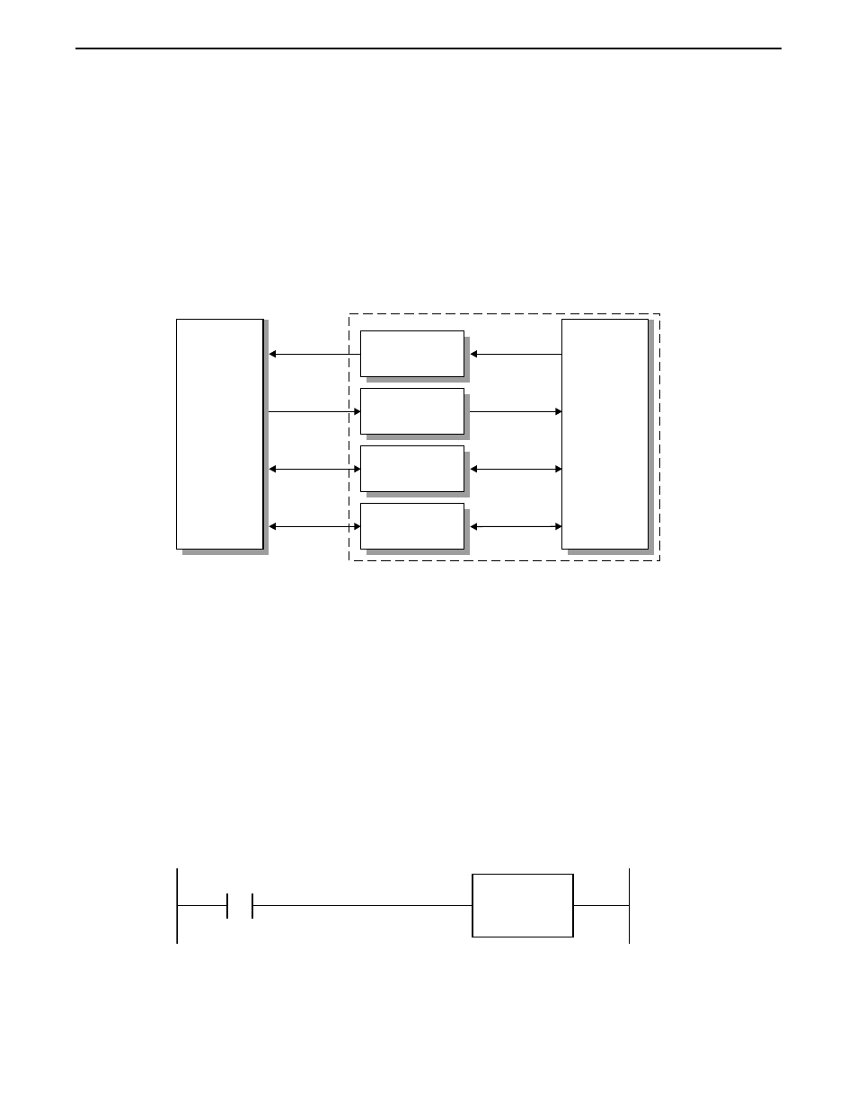
The OIT Family Operator Interface Terminals communicate with PLCs by using
point-to-point serial communications to read from and write to the internal registers and
coils of the PLC. Six sets of registers and coils located within the PLC’s internal memory
are designated for special purposes: the Message Request Register, Current Message
Register, Key coils, Status coils, Status LED coils, and Function Key LED coils.
Message Request Register (MRR)
The MRR is a data register in the PLC that is continuously monitored by the OIT. When
the PLC enters a decimal or BCD number into this register, the OIT:
•
displays the screen that corresponds to that number
(the screen can be a message, recipe, alarm, or menu)
•
performs any special function associated with the screen
(for example, an alarm screen might sound the OIT’s internal buzzer).
•
and optionally sends the screen contents to a serial printer.
For example, you may want Screen #30 to be shown on the OIT whenever input coil X1
is turned on. Screen #30 might read: Oven Door is Open!!!
The relay ladder logic could be the following:
In this case, D500 is the MRR that the OIT has been configured to constantly monitor.
When input coil X1 is activated, the PLC puts the decimal number 30 into the MRR. The
OIT then sees the number 30 in the MRR and displays Screen #30.
Operational Overview
20
1010-0099, Rev. 07
OIT
OIT Reads
Message #
Message Request
Register
PLC Writes
Message #
OIT Writes
Message #
Current Message
Register
PLC Reads
Message #
OIT Reads
& Writes
Status Bit,
Key & Status
LED Coils
PLC Reads
& Writes
OIT Reads
& Writes
Registers
and Coils
PLC Reads
& Writes
PLC
PLC MEMORY
Figure 1: Interaction Between the OIT and PLC
INPUT COIL
Move
Number: 30
Data Register
Location: 500
X1