Decode camera transactions dialog – Teledyne LeCroy FireInspector - Users Manual User Manual
Page 81
71
CATC F
IRE
I
NSPECTOR
2.01
C
HAPTER
5
User’s ManualCATC Trace Fil
es
For more information about the View Fields dialog, please see “View Fields Dialog” on
page 75.
This is the field that contains View Fields options:
•
Type: contains the decoded bit fields of the quadlet that is read/written.
Decode Camera Transactions Dialog
Decoding digital camera transactions requires information that's not necessarily included in
the Trace files. Each camera device has a base address that is unknown to FireInspector, so
that address must be supplied manually. If the device supports Video Format 7 modes, then
it has another bank of registers that FireInspector can decode when supplied with the Video
Format 7 address(es).
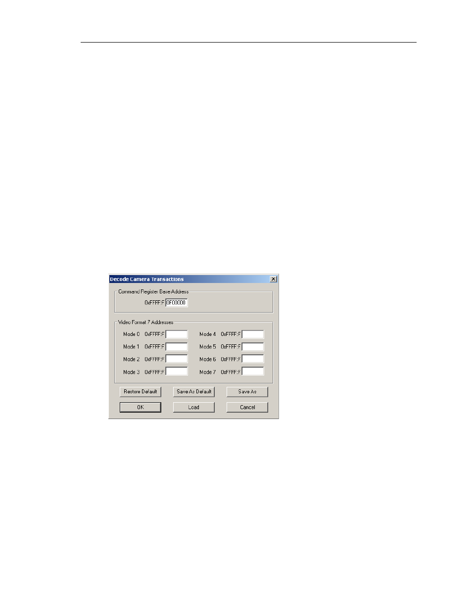
The Decode Camera Transactions dialog (Figure 5-16) is used to supply the missing
information so that the transactions can be decoded and displayed in FireInspector.
To set up decoding parameters for digital camera transactions:
Step 1
Select Setup > Decoding Parameters > Digital Camera Decoding Parameters
from the menu bar.
Step 2
The Decode Camera Transactions dialog will open.
Step 3
Command Register Base Address: Enter the last 28 bits of a Base Address.
By default, the address 0xFFFF:F0F00000 is entered.
Video Format 7 Addresses: Enter up to 8 Mode addresses for cameras that
support Video 7 format. If these are left blank, no Video 7 format decoding
will happen.
All parameters should be entered in hexadecimal.
Step 4
Click OK to apply the settings.
Other options in the Decode Digital Camera Transactions dialog:
Figure 5-16: Decode Camera Transactions dialog