Teledyne LeCroy FireInspector - Users Manual User Manual
Page 61
51
CATC F
IRE
I
NSPECTOR
2.01
C
HAPTER
5
User’s ManualCATC Trace Fil
es
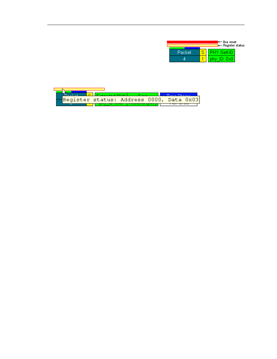
• Bus reset locations
—
A bus reset is indicated by a
red bar in between packet rows.
• Register status
—
If data is read from FireInspec-
tor’s PHY register, it is denoted by a yellow bar
between packet rows. Place the mouse pointer over
the register status bar to access a tooltip that con-
tains the register address and the data that was read.
• Trigger location (if applicable)
—
If a newly recorded file contains a trigger, it is marked
with a red marker bar on the left edge of the number field of the trigger packet. The
marker can be edited or removed, just like any other marker in a Trace file. The packet
number field colors can be set so that the pre- and post-trigger packets are different col-
ors, making them easily distinguishable.
• Subaction gap and arbitration reset gap locations (if applicable)
—
Gaps are denoted by
green (subaction) and blue (arbitration reset) bars on the top edge of the packet number
field.
• Data transfer rates (S)
—
The rate at which the packet’s data was transferred on the bus.
•
1 = 100 Mbps
•
2 = 200 Mbps
•
4 = 400 Mbps
The data transfer rate is the second field in a packet row.
• Transaction codes (Tcode)
—
The name of the packet’s transaction type is displayed in
the top portion of the third field in a packet row.
• Time Stamps
—
Packets are time stamped to an accuracy of 20 nanoseconds. Time
stamps are formatted as Seconds.CycleCount CycleOffset, in units of 125 microseconds.
Seconds increments once per second. CycleCount increments once every bus cycle.
CycleOffset increments once every clock cycle. You can find the elapsed time between
two packets by calculating the difference between their Time Stamp values. The Time
Stamp field occurs last in the packet row.
Note: Due to hardware limitations, short bus packets with length equal to two
quadlets
—
such as PHY packets and GASP or isochronous packets without
a data payload
—
don't have seconds in the time stamp.
Figure 5-8: Register status tooltip
Figure 5-7: Bus reset and register status
markers