4 external interface breakout board, External interface breakout board – Teledyne LeCroy FireInspector - Users Manual User Manual
Page 16
6
CATC F
IRE
I
NSPECTOR
2.01
C
HAPTER
1
User’s ManualFireInspector Overview
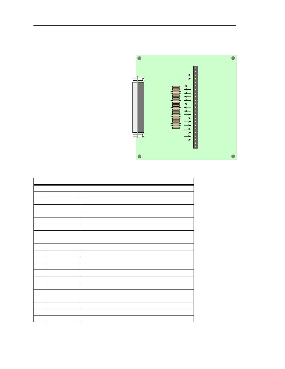
1.4 External Interface Breakout Board
The External Interface Breakout Board,
shown in Figure 1-6, is an accessory that
allows convenient access to nine
potentially useful TTL output signals and
eight TTL input signals. Four ground and
one 5-volt pin are also provided. This
external breakout board also provides a
simple way for connecting logic analyzers
or other tools to the analyzer unit.
The breakout board connects, via a ribbon
cable, to the Data In/Out connector located
on the back of the analyzer box. Each pin is
isolated by a 100
Ω
series resistor and a
74F244 inside the analyzer box.
Signal descriptions for each of the available
pins on the External Interface Breakout
Board are listed in Table 1-2.
Table 1-2: External Interface Breakout Board – Pin Description
Pin
Signal Description
1
GND
Signal Ground
2
GND
Signal Ground
3
5V
5V DC source, limited internally to 500mA (polyswitch fuse)
4
- Trigger Out
Active-low TTL output
5
Not connected
6I 0
Trigger/signal TTL input - programmable as active high or low
7
I 1
Trigger/signal TTL input - programmable as active high or low
8
I 2
Trigger/signal TTL input - programmable as active high or low
9
I 3
Trigger/signal TTL input - programmable as active high or low
10
I 4
Trigger/signal TTL input - programmable as active high or low
11
I 5
Trigger/signal TTL input - programmable as active high or low
12
I 6Trigger/signal TTL input - programmable as active high or low
13
I 7
Trigger/signal TTL input - programmable as active high or low
14
O 0
Signal TTL output - programmable as pulse high/low or toggle
15
O 1
Signal TTL output - programmable as pulse high/low or toggle
16O 2
Signal TTL output - programmable as pulse high/low or toggle
17
O 3
Signal TTL output - programmable as pulse high/low or toggle
18
O 4
Signal TTL output - programmable as pulse high/low or toggle
19
O 5
Signal TTL output - programmable as pulse high/low or toggle
20
O 6Signal TTL output - programmable as pulse high/low or toggle
21
O 7
Signal TTL output - programmable as pulse high/low or toggle
R1
R2
R3
R4
R5
R6
R7
R8
R9
R10
R11
R12
R13
R14
R15
R16
R17
R18
R19
GND
GND
5V
Trigger Out
- - -
I0
I1
I2
I3
I4
I5
I6
I7
O0
O1
O2
O3
O4
O5
O6
O7
GND
GND
1
23
J1
FireInspector
Breakout Board
P1
Figure 1-6: External Interface Breakout Board