Teledyne LeCroy PeRT3 Phoenix System User Manual
Page 68
66
Teledyne LeCroy
System Control Ribbon ‐‐ Options Tab
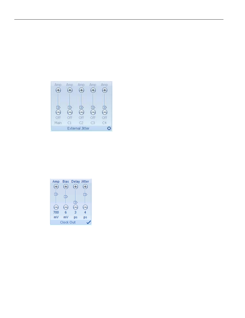
External Jitter
The External Jitter panel is used in combination with the Jitter In connector on the front
panel of the PeRT
3
Phoenix system. This allows the user to introduce other sources of
jitter, and to control how those additional jitter sources are applied to each channel. The
Main control acts as a master amplitude control in applying the external jitter across all
channels. The individual channel controls allow the user to selectively apply the external
jitter to specific channels.
Figure 6.27: External Jitter Panel
Clock Out
The Clock Out panel controls the Clock Out signal which can be used to control external
equipment. These controls allow the user to introduce a delay of 0 to 100 ps, and to
introduce a jitter of 0 to 6 ps into the clock signal.
Figure 6.28: Clock Out Panel
Diagnostics
The Diagnostics panel allows the user to test the operation of system components,
including the digital electronics ("Phoenix R‐6"), the analog front end ("Phoenix FE‐6"),
and correct connectivity between the two sections see
Figure 6.29 on page 67
). The
results of the diagnostics tests are displayed in the Output window.