Teledyne LeCroy PeRT3 Phoenix System User Manual
Page 59
Teledyne LeCroy PeRT
3
Phoenix System User Manual
57
System Control Ribbon ‐‐ Channel Tabs
Teledyne LeCroy
Signal
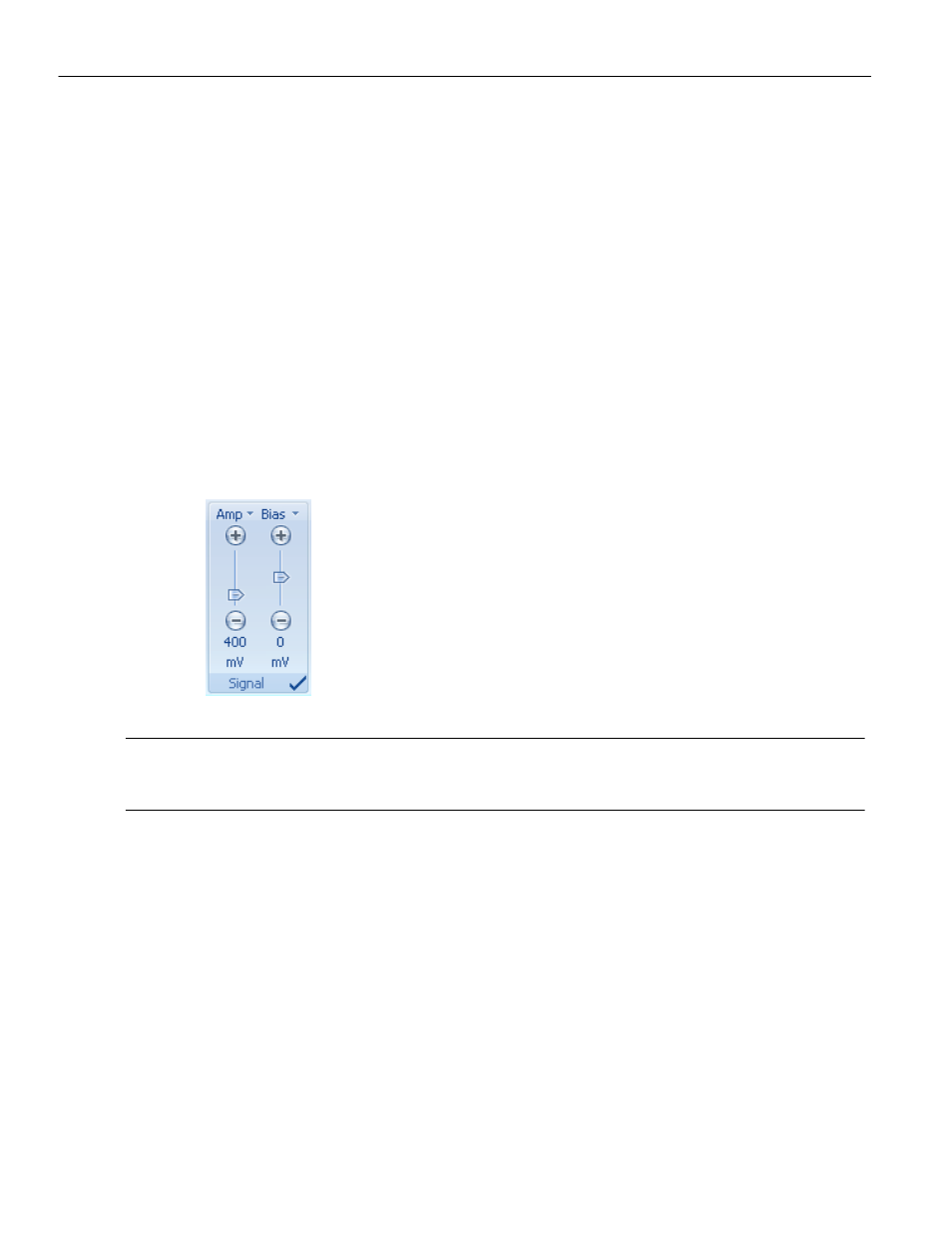
The Signal panel allows the user to control the amplitude and bias of the differential
signal. By default, the Signal panel is inactive (turned off) when the system is first turned
on, as shown by the circle in the lower right corner of the panel. Before any testing can
take place, the user must turn this on (click to change to a check mark) and specify the
desired signal characteristics.
Signal amplitude (Amp) can be controlled over the range from 100 mV to 2200 mV in
increments of 5 mV. Signal amplitude is the nominal voltage of the differential signal, and
is a measure of the overall signal power. Low signal amplitude can be used to test for the
limits of receiver sensitivity (additional losses due to connectors and cables should be
taken into account). High signal amplitudes can be used to test for receiver saturation or
even damage limits to electronics.
Signal bias can be controlled over the range ‐1800 mV to +1800 mV in increments of 5 mV.
Signal bias is the offset (from ground) that is applied to the differential signal, or in other
words, the DC component of the signal.
Figure 6.16: Signal Panel
Note:
All signal impairment controls are turned off by default. All controls must first be turned on by
clicking the circle in the bottom right corner of each panel. When the control is active, the circle
will change to a check mark
De-Emphasis
The Emphasis panel allow the user to control the 3 tap emphasis setting on the transmit
signal. The transmit emphasis consisting of De‐emphasis and PreShoot. By Default,
emphasis is turned off (see
Figure 6.17 on page 58
).
De‐emphasis (DeE) values can be controlled over the range from ‐12dB to 0dB with 0.1dB
resolution (nominal values) and PreShoot (PreSht) can be controlled over the range 0dB
to 9dB with 0.1dB resolution (nominal values). De‐emphasis and PreShoot can be added
independently for effects of a full bit 2‐tap equalizer or be added simultaneously as a full
bit 3‐tap equalizer. Both values are calibrated based on the PCIE Gen3 Transmitter
equalization calibration methodology and should be calibrated before each test based on
the channel applied to the test system.