Teledyne LeCroy PeRT3 Phoenix System User Manual
Page 66
64
Teledyne LeCroy
System Control Ribbon ‐‐ Options Tab
default the PeRT
3
inserts these at the correct interval. But the user may want to disable
this feature if the device under test was not working with the standard ALIGN frequency.
In such a case the user might still want to test the device by creating their own custom
pattern that had more (or less) frequent ALIGNs in them. In that case the SATA align
verification could be turned off, and the PeRT
3
would send the pattern exactly as the user
specifies it without inserting additional ALIGNs in the pattern specified (the PeRT
3
would
still ignore ALIGNs inserted or removed by the DUT for purposes of BER calculation.)
If doing simple BER testing in Custom mode, no pattern validation will take place,
because there are no requirements placed on a pattern in Custom mode. There is no
need to turn off pattern validation in this case.
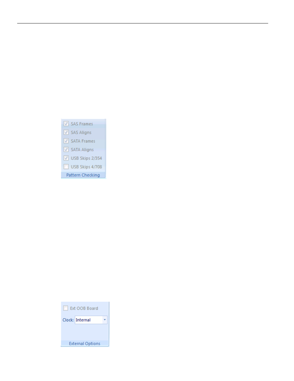
Figure 6.24: Pattern Checking Panel
External Options
The External Options panel allows the user to specify the use of an external switching
board and/or an external reference clock.
The External OOB Board is a connection board that provides rapid OOB signal switching
under the control of the PeRT
3
hardware. The OOB Board connects via the 25‐pin
auxiliary connector on the lower right of the PeRT
3
Phoenix front panel.
For most applications and devices, the internal PeRT
3
hardware is able to perform OOB
signaling. However, some SATA hosts are not compliant with the SATA specification, and
for those specific host machines the external OOB board is required in order to use the
PeRT
3
to initialize those devices. It is not required for SATA devices, or if testers have
external means of putting the SATA host into loopback mode, or if the SATA host adheres
to the SATA specifications for loopback.
Figure 6.25: External Options Panel