Teledyne LeCroy PeRT3 Phoenix System User Manual
Page 61
Teledyne LeCroy PeRT
3
Phoenix System User Manual
59
System Control Ribbon ‐‐ Channel Tabs
Teledyne LeCroy
(10
12
) transitions will have 14 times as much jitter (or 56% of the unit interval in the case
of 4% RMS).
The Low Frequency Random Jitter is generated by passing the random source through a
low pass filter as called for in the PCIe compliance specification. The resulting jitter is
bandwidth limited and will not necessarily be measured as "random" jitter on many
scopes or other jitter measurement tools and packages that define random jitter as jitter
with a flat frequency spectrum and use frequency analysis to separate random jitter from
deterministic jitter. The High Frequency Random Jitter source, on the other hand, is not
frequency limited and will appear as random jitter when measured by such instruments.
The Very High Frequency Random Jitter is generated by passing the random source
through a bandpass filter as called for in the PCIe Gen3 compliance specification.
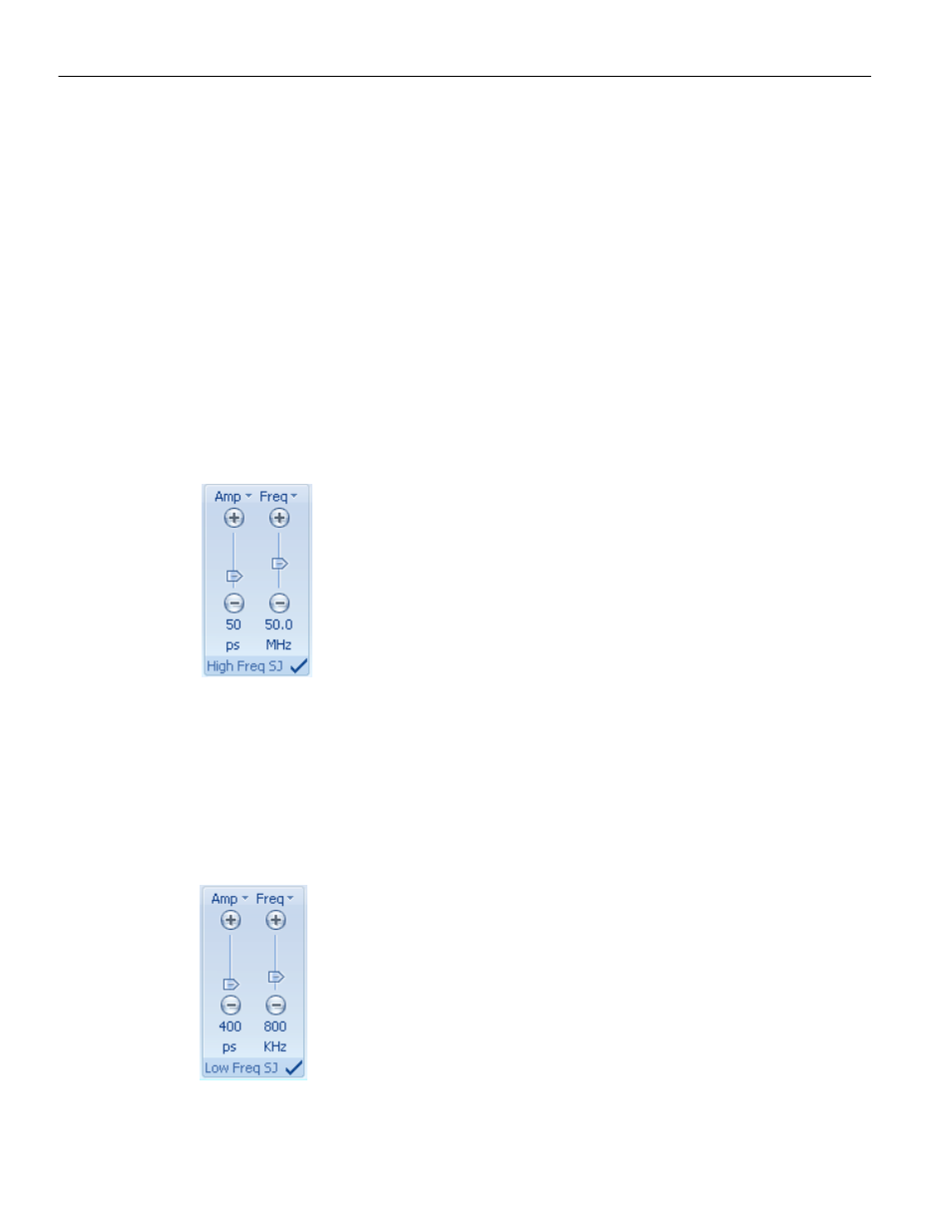
High Frequency Sinusoidal Jitter
The High Frequency Sinusoidal Jitter panel ("High Freq SJ") allows the introduction of
periodic jitter at controlled frequencies and amplitudes.
Figure 6.19: High Frequency Sinusoidal Jitter Panel
Low Frequency Sinusoidal Jitter
Low Frequency SJ extends the lower frequencies range available on the Phoenix. Low
Frequency SJ is generated through modulating the clocks, compared to the modulation
achieved through the delay line used to generate High Frequency Jitter.
For Jitter range of SJ, please refer to the PeRT
3
Phoenix Data Sheet.
Figure 6.20: Low Frequency Sinusoidal Jitter Panel