Grid area – Teledyne LeCroy WaveRunner XI SERIES Operator’s Manual User Manual
Page 36
W
AVE
R
UNNER
X
I
S
ERIES
Grid Area
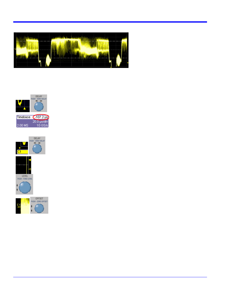
The grid area contains several indicators to help you understand triggering. Indicators are coded to the channel
colors (yellow here for channel 1).
Trigger Delay - This indicator is located along the bottom edge of the grid. Trigger delay
allows you to see the signal prior to the trigger time.
All trigger delay values (including post-trigger delay, shown here) are displayed in the
Timebase descriptor label. Zero delay is the horizontal center of the oscilloscope display.
The default setting (
Time) is for the delay to be read out in seconds, and to move
proportionately when the timebase knob is turned. If you want to set delay (
Div) to a fixed
position on the grid and then have it stay fixed as the timebase changes, go to
Utilities,
Preferences, Acquisition.
Post-trigger Delay - This is indicated by a left-pointing arrow below-left of the grid. Pre-
trigger delay is indicated by a right-pointing arrow below-right of the grid.
Trigger Level - This indicator is located at the right edge of the grid. It tracks the trigger
level as you reposition the trace up or down, or change scale. When triggering is stopped,
a hollow arrow indicates where the new level will be when triggering resumes.
Push the
L
EVEL
knob to reset the level to 50%.
Zero Volts Level - This indicator is located at the left edge of the grid. To change the zero
volts level, turn the
V
ERTICAL
O
FFSET
knob. Push the knob to reset the indicator to the
middle of the grid.
36
WRXi-OM-E Rev C