4 operation timings, 1 timing after power on – IAI America PCON-SE User Manual
Page 67
55
4. Description of Operating Functions
4.4 Operation
Timings
4.4.1
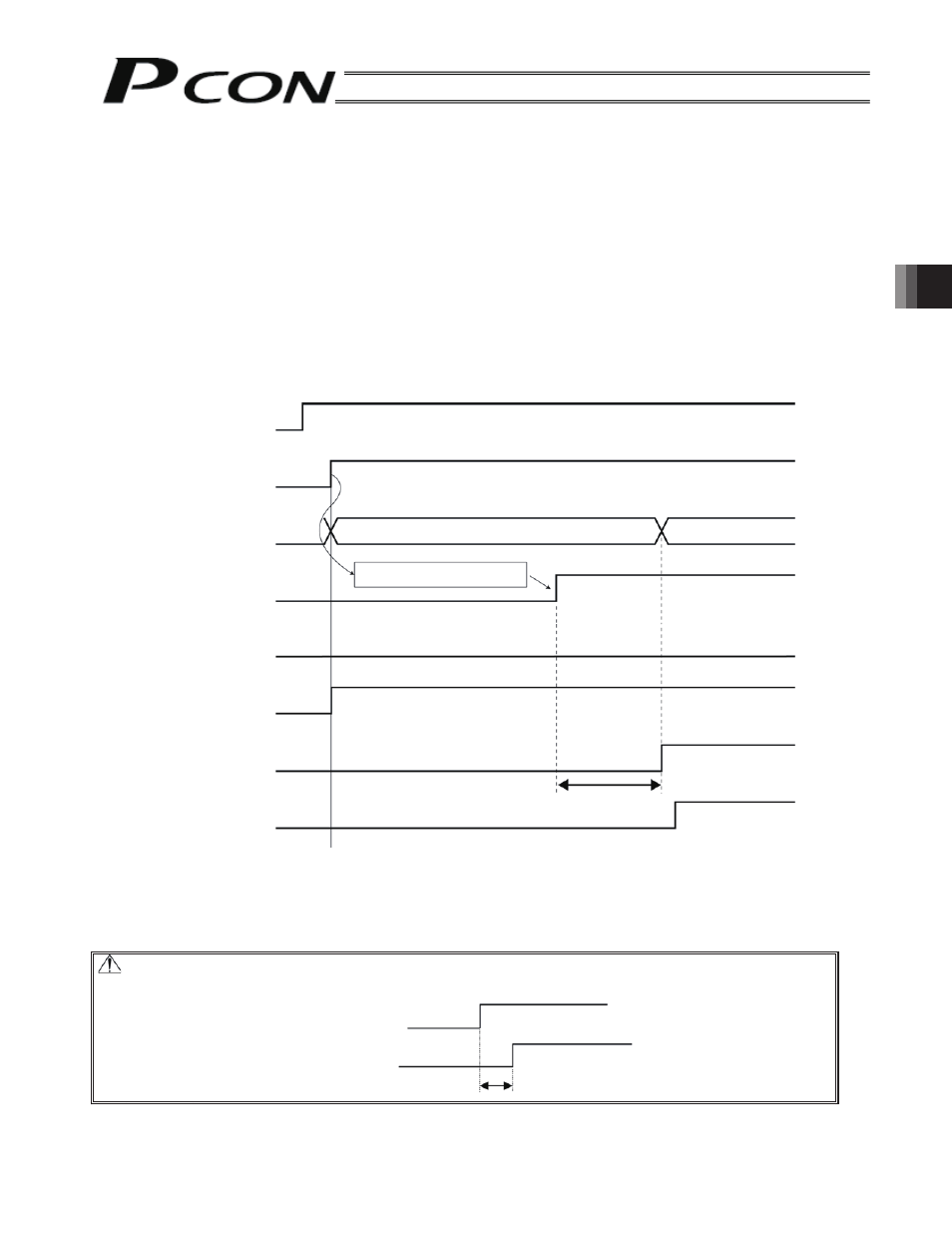
Timing after Power ON
After conforming that the slider or rod is not contacting the mechanical end or transferred work is not interfering
with peripheral equipment, start operation following the steps below.
[1] Reset the emergency stop condition or put the motor drive power into a current-accessible state.
[2] Supply of 24 VDC of controller power supply: 24 V terminal, 0V terminal on the power supply terminal block
When 24 VDC is supplied in an emergency stop reset state, the controller is automatically put into the servo
ON condition internally.
[3] Initial setting of parameters (min.)
(Example)
y To change the feed speed during teaching:
Change the value of the parameter No. 35 (safety speed).
[4] Set the optimum values in the fields of “Position,” “Speed,” “Acceleration,” “Deceleration,” etc., with the PC or
teaching pendant.
(Note 1) T1: Excited-pole detection time = 0.2 to 12 sec
Normally the detection of excited pole completes in approx. 0.2 sec, although the exact time varies
from one actuator to another due to individual differences and also depending on the load
condition. If the detection of excited pole has failed, the excited-pole detection operation will be
continued for up to 12 sec.
Caution: For the timing of emergency stop reset after power-on from the emergency stop condition,
the servo will be turned ON in T1 (Note 1) sec at maximum after emergency stop reset.
Safety circuit condition
Emergency stop is reset
Illuminates in orange only for 2 sec and then goes out.
Initial parameter settings
Pause is cancelled
Initial state
͆1͇
Green
170 msec or less
Controller power supply
24 VDC power ON
SV lamp (Front panel)
Controller ready output (PWR)
Pause input (STP)
Servo ON command (SON)
Operation ready (SV)
Position complete output
(PEND)
Emergency stop is reset
Servo ON condition
T1 (Note 1)