IAI America PCON-SE User Manual
Page 37
25
2. Specifications
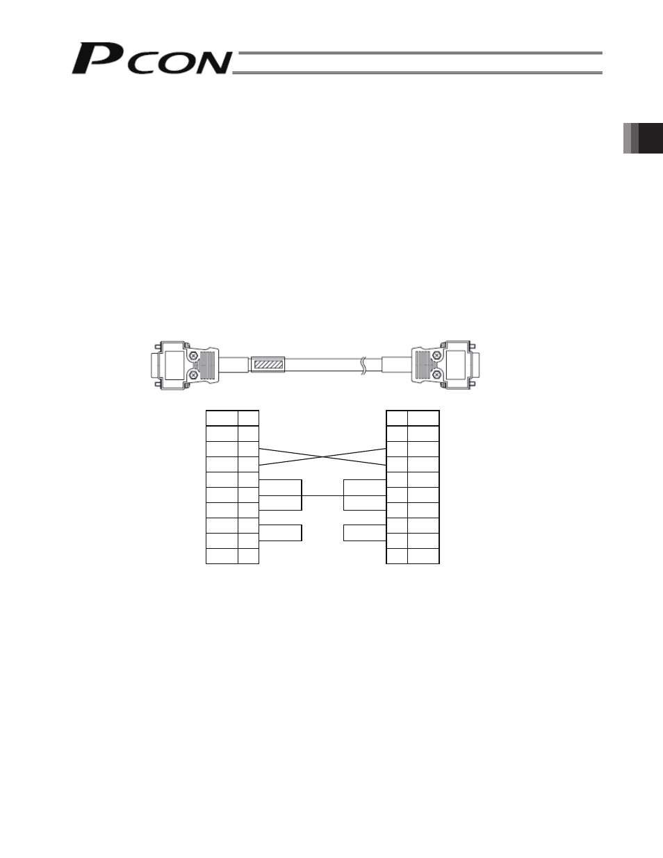
[4] D-sub, 9-pin connector (RS232C)
A connection port with the PLC’s communication module. A PC can also be connected to this port. For the
communication cable, use the RS232C cross cable specified below.
[5] Mini DIN, 8-pin connector (RS485)
A connection port with the teaching pendant or PC. For the communication cable, use the cable (with
RS232C/RS485 converter) supplied with the PC software (RCM-101-MW).
[6] PORT switch
A switch for enabling/disabling the mini DIN connector. Set the switch to ON when an equipment is
connected to the mini DIN connector, or OFF when no equipment is connected.
[7] Monitor LEDs
LED1 --- This LED illuminates while the controller is sending data.
LED2 --- This LED illuminates while the RS232 is sending data.
(Reference) Connection diagram of RS232C cross cable (commercial product)
d
n
e
C
P
d
n
e
r
e
t
r
e
v
n
o
c
O
I
S
r
o
t
c
e
n
n
o
c
n
i
p
-
9
,
b
u
s
-
D
r
o
t
c
e
n
n
o
c
e
l
a
m
e
f
n
i
p
-
9
,
b
u
s
-
D
No.
1
2
3
4
5
6
7
8
9
Signal
RD
SD
DTR
SG
DSR
RS
CS
Signal No.
1
RD
2
SD
3
DTR
4
SG
5
DSR
6
RS
7
CS
8
9
(Female if a PC is connected,
or male if a PLC is connected)