IAI America PCON-SE User Manual
Page 51
39
3. Installation and W
iring
Apply pressure.
Locking tab
Cable tube
Double shielded twisted-pair
shielded
e-CON connector
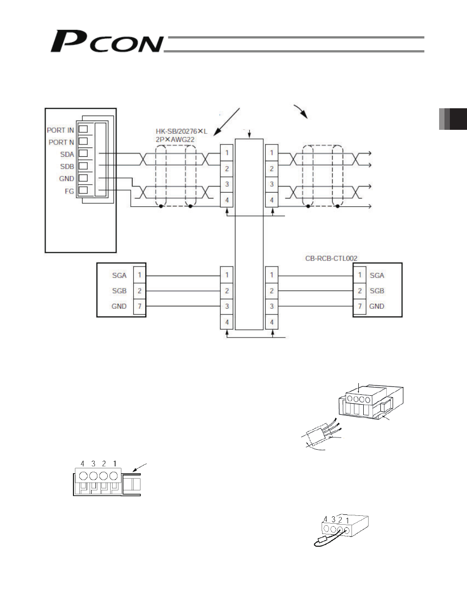
Detailed Connection Diagram
Connection details of SIO communication are shown below. The controller link cable is available as an option,
but the communication trunk line must be prepared by the customer.
Ŷ
Preparation of Communication Main Line
[1] Strip the sheath of a double shielded twisted-pair cable by
approx. 15 to 20 mm.
[2] Place a cable protection tube over the cable.
[3] Insert the three wires into the cable insertion holes in the
connector without stripping the core sheath.
[4] With the cable inserted in the press-fit cable housing, apply
pressure from above to pressure-weld the core wires.
[5] Heat-treat the cable protection tube.
e-CON connector pin numbers
Be sure to insert a terminal resistor (220
Ω, 1/4 W) at the terminal end of the communication trunk line
(between pins 1 and 2 of the e-CON connector)
Locking tab
Gateway Unit
Paired shielded cable
Recommended: Taiyo
Cabletec
Yellow
Orange
Blue
Axis 1
SIO communication
trunk line
4-way junction (AMP: 5-1473574-4)
e-CON connector (AMP: 4-1473562-4)
Housing color: Green
Controller link cable
Yellow
Orange
Blue
1st unit
2nd unit
e-CON connector (AMP: 3-1473562-4)
Housing color: Orange