2) when the gateway unit is used, 34 3. installation and w iring, Pcon-se controller – IAI America PCON-SE User Manual
Page 46
34
3. Installation and W
iring
(2)
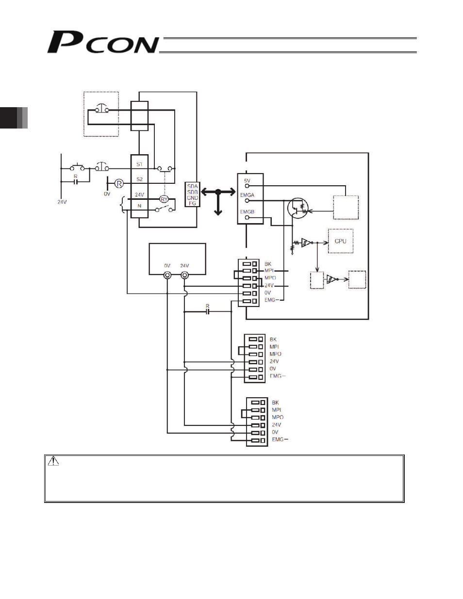
When the gateway unit is used
Caution: [1] The input current to the EMG terminal of PCON-SE is 5 mA. When connecting the
contact of the EMG relay R to the EMG terminals of multiple controllers, check the
current capacity of the relay contact.
[2] Make the 0V of the gateway unit power supply and PCON-SE power supply in
common.
Gateway unit
Gateway
power supply
Port switch
Teaching pendant
EMG push
button
T.P. connector
PCON-SE controller
EMG reset
switch
EMG push
button
SIO
communication
SIO connector
SIO
connector
connection
detecting
circuit
Connection
detecting
signal (H)
Drive stop
signal (L)
Ti
m
e
constan
t
Control
power
supply
Power supply terminal block
Power supply terminal block (Unit 2)
EMG signal
detection
(H)
Motor drive
power
supply
Motor
drive
circuit
Power supply terminal block (Unit 3)
Input power supply
24 VDC
(2 A max. per unit)
- ERC2 (138 pages)
- ERC2 (188 pages)
- ERC3 (438 pages)
- ERC (153 pages)
- RCA-E (53 pages)
- RCA-P (42 pages)
- RCB-101-MW (38 pages)
- RCP2-C (178 pages)
- RCS-E (102 pages)
- RCA-A4R (72 pages)
- RCA-RA3C (114 pages)
- RCA-SRA4R (56 pages)
- RCA2-RA2AC (100 pages)
- RCA2-SA2AC (92 pages)
- RCA2-TA4C (134 pages)
- RCD-RA1D (40 pages)
- RCP2-BA6 (72 pages)
- RCP2-GRSS (130 pages)
- RCP2-HS8C (126 pages)
- RCP2-RA2C (120 pages)
- RCP2-RTBS (80 pages)
- RCP2W-SA16C (46 pages)
- RCP3-RA2AC (60 pages)
- RCP4-RA5C (82 pages)
- RCP4-SA5C (94 pages)
- RCP4W (96 pages)
- RCS2-F5D (142 pages)
- RCS2-GR8 (46 pages)
- RCS2-RN5N (80 pages)
- RCS2-RT6 (60 pages)
- RCS2-SA4C (258 pages)
- RCS2-TCA5N (62 pages)
- RCL-SA1L (66 pages)
- RCL-RA1L (56 pages)
- RCLE-GR5L (46 pages)
- IK Series (16 pages)
- FS (84 pages)
- IF (76 pages)
- ISB (114 pages)
- ISDA (126 pages)
- ISDB (116 pages)
- ISPWA (90 pages)
- ICS(P)A (16 pages)
- NS (78 pages)
- RS (46 pages)