2 name and function of each part of the controller – IAI America PCON-SE User Manual
Page 33
21
2. Specifications
2.2
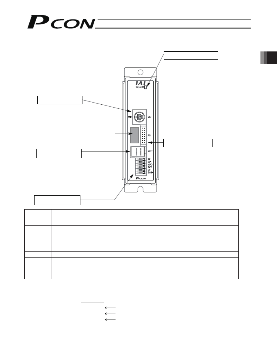
Name and Function of Each Part of the Controller
BK
Terminal for connecting the brake release switch to forcibly release the brake when the
actuator is used with a brake option.
Connect the opposite side of the switch to 24 V.
MPI, MPO
A contact for cutting off motor drive power supply with safety category 1 or equivalent
considered.
MPI and MPO represent the input side and output side of the motor power supply,
respectively. (Short these terminals using a jumper wire if not used. The controller is shipped
with MPI and MPO shorted.)
24 V
Positive side of the 24 VDC input power supply
0V
0V side of the 24 VDC input power supply
EMG
−
Terminal for connecting the emergency stop circuit (motor drive signal shutdown).
With the grounding common, connect the opposite side of the emergency stop switch (or
contact) to the negative side of the 24 VDC input power supply.
Ŷ
Notation of the actuator type connected
The type name, ball screw lead length, and stroke of the actuator are indicated. Before connecting cables,
confirm that the actuator is an appropriate one.
Notation example:
Connector for the encoder cable
Connector for the teaching
pendant/PC, gateway unit
and SIO converter
The model of the actuator
connected is displayed here.
Connector for the motor cable
Power terminal block
SIO connector
Motor connector
Status indicator LEDs
SV (green): Indicates the servo ON status.
When this LED is blinking, the
controller is in the auto servo
OFF mode.
ALM (red): Indicates the alarm generated
status or emergency stop
status.
Encoder connector
RA4C
L: 5mm
ST: 200
Indicates the actuator type is RA4C.
Indicates the ball screw lead length is 5mm.
Indicates the stroke is 200 mm.