9 connecting the actuator, 1 motor relay cable – IAI America PCON-SE User Manual
Page 47
35
3. Installation and W
iring
3.9 Connecting
the
Actuator
3.9.1
Motor Relay Cable
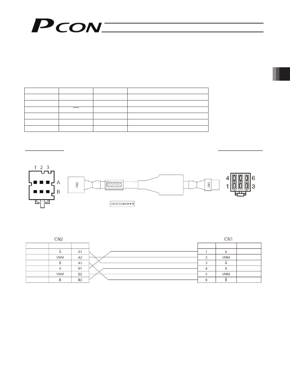
• Connect the motor relay cable to the MOT connector.
Signal table for controller-end connector (CN2)
Pin No.
Signal
Wire color
Description
A1
A
Orange
Motor drive line (phase A-)
A2 VMM
Gray
Motor power line
A3
B
White
Motor drive line (phase B-)
B1 A
Yellow
Motor drive line (phase A+)
B2 VMM Pink
Motor power line
B3 B
Yellow (Green)
Motor drive line (phase B+)
Housing: 1-1318119-3
(AMP)
Receptacle contact: 1318107-1
Housing: SLP-06V
(JST)
Socket contact: BSF-21T-P1.4
Pin arrangements of CN2
Controller end
Actuator end
Cable color
Signal name
Pin No.
Pin arrangements of CN1
Cable color
Signal name
Pin No.
Orange
Gray
White
Yellow
Pink
Yellow (Green)
Yellow
Gray
Orange
Yellow (Green)
Pink
White
- ERC2 (138 pages)
- ERC2 (188 pages)
- ERC3 (438 pages)
- ERC (153 pages)
- RCA-E (53 pages)
- RCA-P (42 pages)
- RCB-101-MW (38 pages)
- RCP2-C (178 pages)
- RCS-E (102 pages)
- RCA-A4R (72 pages)
- RCA-RA3C (114 pages)
- RCA-SRA4R (56 pages)
- RCA2-RA2AC (100 pages)
- RCA2-SA2AC (92 pages)
- RCA2-TA4C (134 pages)
- RCD-RA1D (40 pages)
- RCP2-BA6 (72 pages)
- RCP2-GRSS (130 pages)
- RCP2-HS8C (126 pages)
- RCP2-RA2C (120 pages)
- RCP2-RTBS (80 pages)
- RCP2W-SA16C (46 pages)
- RCP3-RA2AC (60 pages)
- RCP4-RA5C (82 pages)
- RCP4-SA5C (94 pages)
- RCP4W (96 pages)
- RCS2-F5D (142 pages)
- RCS2-GR8 (46 pages)
- RCS2-RN5N (80 pages)
- RCS2-RT6 (60 pages)
- RCS2-SA4C (258 pages)
- RCS2-TCA5N (62 pages)
- RCL-SA1L (66 pages)
- RCL-RA1L (56 pages)
- RCLE-GR5L (46 pages)
- IK Series (16 pages)
- FS (84 pages)
- IF (76 pages)
- ISB (114 pages)
- ISDA (126 pages)
- ISDB (116 pages)
- ISPWA (90 pages)
- NS (78 pages)
- ICS(P)A (16 pages)
- RS (46 pages)