1 description of position table – IAI America PCON-SE User Manual
Page 56
44
4. Description of Operating Functions
4.1
Description of Position Table
A position table is created by using the PC software or teaching pendant.
For its usage, refer to each operation manual.
In this section, a position table is explained by taking the PC software screens as examples.
(In the case of the teaching pendant, the display contents are different.)
No.
Position
[mm]
Speed
[mm/s]
Acceleration/deceleration
[G]
Deceleration
[G]
Push
[%]
Threshold
[%]
Positioning
band [mm]
0 5.00
300.00
0.30
0.30 0 0
0.10
Î
1 380.00 300.00
0.30
0.10 0
0
0.10
2 200.00 300.00
0.30
0.10 0
0
0.10
Zone +
[mm]
Zone –
[mm]
Acceleration mode
Incremental
Command
mode
Stop mode
Comment
Î
100.00 0.00
0
0
0
4
400.00 300.00
0
0
0
0
250.00 150.00
0
0
0
0
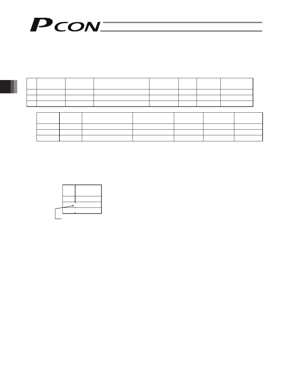
(1) No.: Indicate the position data number.
(2) Position: Enter the target position to move the actuator to, in [mm].
Absolute coordinate specification: Enter the distance to the target actuator position from the home.
Relative coordinate specification: Under the assumption of a constant pitch, a relative amount from the
current position is indicated.
No.
Position
[mm]
0
5.00
Absolute coordinate specification: 5 mm from the home
1
10.00
Relative coordinate specification: +10 mm from the current position
2
-10.00
Relative coordinate specification: -10 mm from the current position
* Indicates the relative coordinate specification with the teaching pendant (RCM-T).
(3) Speed: Enter the speed at which the actuator will be moved, in [mm/sec].
The default value varies depending on the actuator type.
=
=