3 pulse counter inputs, 2 analog inputs, 1 4…20 ma inputs – Burkert Type 8620 User Manual
Page 62: Configuration (code level: specialists), A/d-conversion
mxCONTROL Type 8620
Page 62
12.1.3 Pulse Counter Inputs
The pulse counter inputs, for example, can be used in combination with the Batch Dosing modules.
The incoming pulses are counted and scaled for further processing per K-Factor. The K-Factor
specifies the amount of pulses per volume unit. The K-Factor can specified in different units - please
refer to the "Configuration" section (see below) for the available units.
Configuration (Code Level: Specialists)
Configuration
Access
via Cfg.-
menu
Access
via XML-
Cfg.-File
Abbre-
viation
(menu)
Value range
Default values
(after factory reset or at
start of Cfg-File-
Download)
Enabling /
disabling input
rw rw Input
On/Off
Off
Unit K-Factor
rw
rw
K-Factor
Unit
(Pulses per) …
L, m³, Gal US, bbl US, gal
Imp, ft3, Pulse
Pulses per L
K-Factor
rw
rw
K-Factor
0.001 … 9999.0
1.0
12.2 Analog
Inputs
The analog inputs are configurable either as 4…20 mA inputs or as Pt100 inputs via the configuration
file for defined hardware versions.
For details please refer to the following sections.
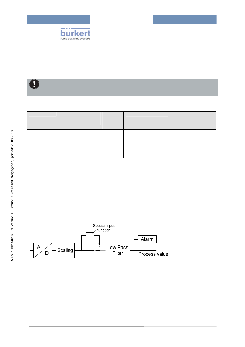
12.2.1 4…20 mA Inputs
Figure 16:
4…20 mA Input
A/D-Conversion
The enabled analog 4...20 mA inputs are sampled every 50 ms with a resolution of 10 bit in order to
convert the analog input signal to a digital value.
Additionally the enabled analog 4...20 mA inputs are checked after each sampling process on:
• input fault (current less than approx. 3.5 mA)
• sensor fault (current greater than approx. 20.5 mA)
• AD-fault (fault during sampling process).
• A calibration data fault is treated as an input fault.
Only the number of incoming pulses is indicated at pulse counter inputs in the menu item
"Process data" \ "Inputs". The display starts with 0 again if more than 99999 pulses are
counted.