Power level accuracy check – Atec Agilent-8563E User Manual
Page 6
Operation Verification
ESG Family Signal Generators
Verification Procedures
2-4
Calibration Guide
4. For frequencies
≥
10 MHz:
a. Press
Amplitude
. Enter 0 using the numeric keypad and press the
dBm
terminator
softkey.
b. Check that the
RF ON
annunciator is displayed. If not, press
RF On/Off.
Configure the Frequency Counter
1. For frequencies < 10 MHz use Input 2. Press
1 M
Ω
.
2. For frequencies
≥
10 MHz and
≤
500 MHz use Input 2. Press
50
Ω
.
3. For frequencies > 500 MHz use Input 1. Press
AUTO
.
NOTE
Set the gate time of > 5 seconds for maximum counter accuracy. Verify that
the counter is phase-locked to the 10 MHz external reference.
Measure the Frequency Accuracy
1. Set the signal generator to the frequencies shown in
Table 2-1, “Frequency Accuracy,”
on page 2-10 (to the maximum frequency of your signal generator).
2. Record the measured frequency in
and compare it to the corresponding limits.
4. Power Level Accuracy Check
Performing this check will provide a high level of confidence that the signal generator’s
power level circuitry is functioning correctly. This check does not test the signal generator
to warranted specifications. Test points have been reduced and the limits are degraded in
order to minimize measurement time and take into account a broad range of measurement
uncertainties. To have the signal generator tested to warranted specifications, a complete
power level accuracy performance test is required. If the complete performance test is
needed and you are unable to perform it, contact your nearest Agilent Technologies service
center for information concerning calibration.
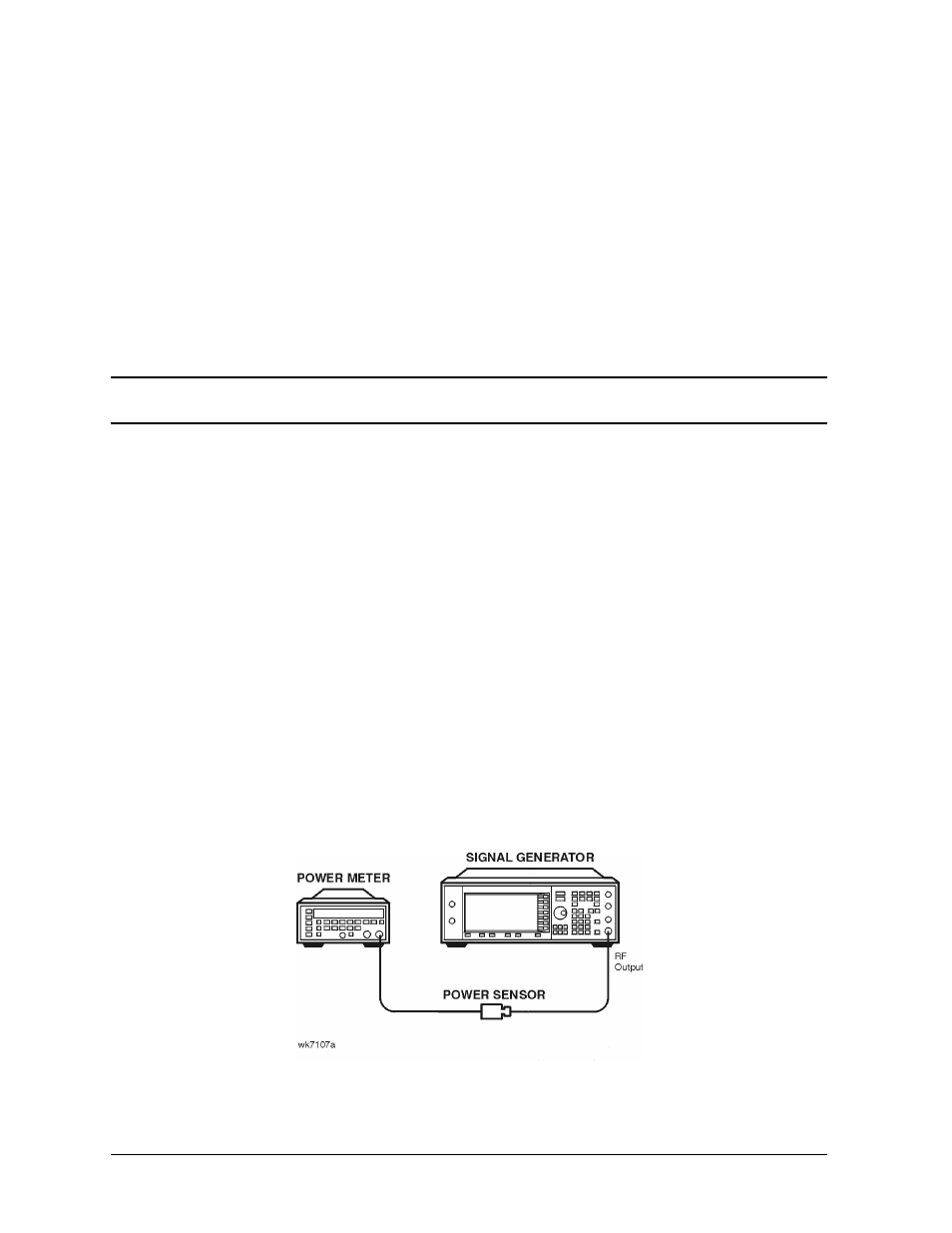
Connect the Test Equipment for Setup 1
Figure 2-2 Power Level Accuracy Equipment Setup 1