Internal source calibration, Description, Required test equipment – Atec Agilent-8563E User Manual
Page 104: Procedure
ESG Family Signal Generators
Adjustments
Internal Source Calibration
Calibration Guide
5-7
Internal Source Calibration
Description
This test is used to calibrate the internal source amplitude versus frequency. The values
for offset and gain are set to their default values in the internal source calibration arrays.
Next, the offset calibration factor is determined by connecting the DVM to the ABUS and
measuring the dc offset of the motherboard common ground ABUS node and the offset of
the DSP ABUS node with the DSP set to 0 Vdc. The calibration factor is the difference
between these two measurements. The scaling factors are determined by setting the DSP
to output a full-scale sinewave with the DVM connected to the front panel LF OUTPUT
port. Measurements are then made in 1 kHz steps and the calibration factors are
calculated to achieve 2 V
peak
on the motherboard by accounting for the nominal gain
presented by the reference board. Upon completion, the calibration factors are stored in
the signal generator’s firmware.
Required Test Equipment
• HP/Agilent 3458A Digital Multimeter
Procedure
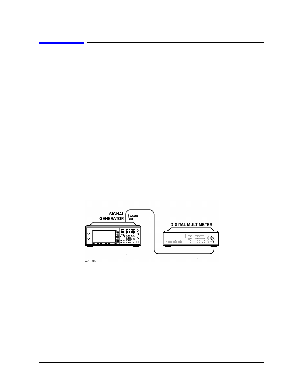
Figure 5-4 Internal Source Calibration Setup
1. Connect the equipment as shown above.
2. Preset all of the equipment.
3. Follow the instructions as they appear on the controller’s display.