Burst modulator calibration, Description, Required test equipment – Atec Agilent-8563E User Manual
Page 124: Procedure, Burst modulator calibration (esg-d only)
ESG Family Signal Generators
Adjustments
Burst Modulator Calibration (ESG-D only)
Calibration Guide
5-27
Burst Modulator Calibration (ESG-D only)
Description
This test is used to adjust the bias modulator circuitry to provide an accurate logarithmic
drop in power level for a linear input voltage. When properly adjusted, a one-volt signal on
the input will result in a 10 dB drop in power level. The adjustment involves the
adjustment of three DACs (BURST BIAS, BURST GAIN, and BURST OFFSET) at several
different frequencies. The BURST OFFSET DAC sets the initial current level through the
burst modulator diode. The BURST GAIN DAC is used to calibrate the input voltage level
to the burst driver circuit. The BURST BIAS DAC sets the breakpoint at which the
modulator switches from a logarithmic to a linear transfer function. The results are stored
in the calibration arrays associated with each DAC.
Required Test Equipment
• HP/Agilent 8904A Function Generator (used as audio source)
• HP/Agilent 8563E Spectrum Analyzer
• HP/Agilent E4400-60073 Digital Test Card
• HP/Agilent 3458A Digital Multimeter
Procedure
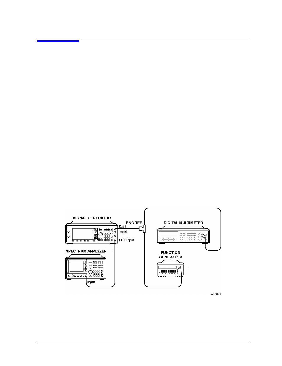
Figure 5-23
Burst Modulator Calibration Setup
1. Connect the equipment as shown above.
2. Preset all of the equipment.
3. Follow the instructions as they appear on the controller’s display.