Pin change mask register 1 – pcmsk1, Pin change mask register 0 – pcmsk0, Atmega169v/l – Rainbow Electronics Atmega169L User Manual
Page 77
77
ATmega169V/L
2514A–AVR–08/02
• Bit 0 – INTF0: External Interrupt Flag 0
When an edge or logic change on the INT0 pin triggers an interrupt request, INTF0
becomes set (one). If the I-bit in SREG and the INT0 bit in EIMSK are set (one), the
MCU will jump to the corresponding Interrupt Vector. The flag is cleared when the inter-
rupt routine is executed. Alternatively, the flag can be cleared by writing a logical one to
it. This flag is always cleared when INT0 is configured as a level interrupt.
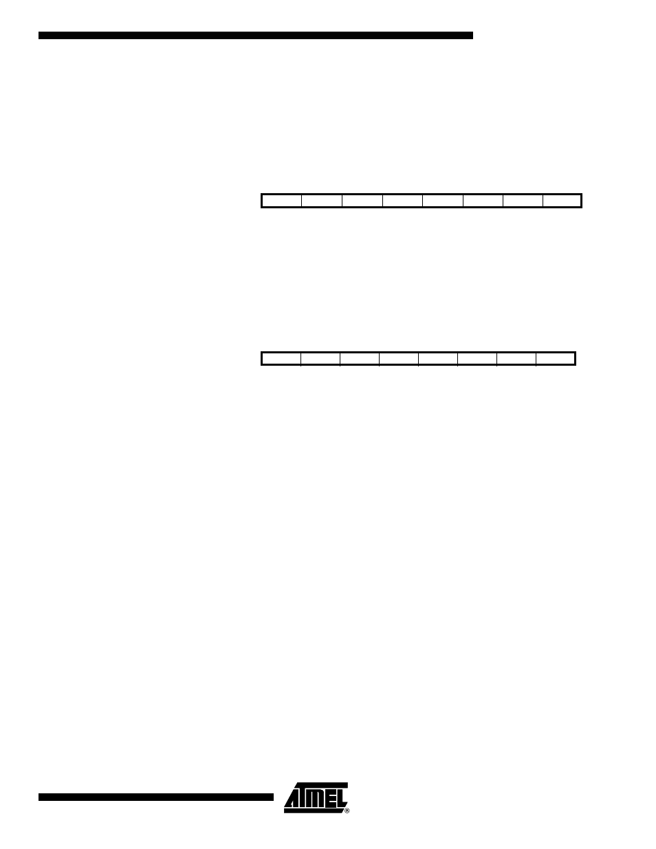
Pin Change Mask Register 1 –
PCMSK1
• Bit 7..0 – PCINT15..8: Pin Change Enable Mask 15..8
Each PCINT15..8-bit selects whether pin change interrupt is enabled on the correspond-
ing I/O pin. If PCINT15..8 is set and the PCIE1 bit in EIMSK is set, pin change interrupt
is enabled on the corresponding I/O pin. If PCINT15..8 is cleared, pin change interrupt
on the corresponding I/O pin is disabled.
Pin Change Mask Register 0 –
PCMSK0
• Bit 7..0 – PCINT7..0: Pin Change Enable Mask 7..0
Each PCINT7..0 bit selects whether pin change interrupt is enabled on the correspond-
ing I/O pin. If PCINT7..0 is set and the PCIE0 bit in EIMSK is set, pin change interrupt is
enabled on the corresponding I/O pin. If PCINT7..0 is cleared, pin change interrupt on
the corresponding I/O pin is disabled.
Bit
7
6
5
4
3
2
1
0
PCINT15
PCINT14
PCINT13
PCINT12
PCINT11
PCINT10
PCINT9
PCINT8
PCMSK1
Read/Write
R/W
R/W
R/W
R/W
R/W
R/W
R/W
R/W
Initial Value
0
0
0
0
0
0
0
0
Bit
7
6
5
4
3
2
1
0
PCINT7
PCINT6
PCINT5
PCINT4
PCINT3
PCINT2
PCINT1
PCINT0
PCMSK0
Read/Write
R/W
R/W
R/W
R/W
R/W
R/W
R/W
R/W
Initial Value
0
0
0
0
0
0
0
0