Atmega169v/l – Rainbow Electronics Atmega169L User Manual
Page 247
247
ATmega169V/L
2514A–AVR–08/02
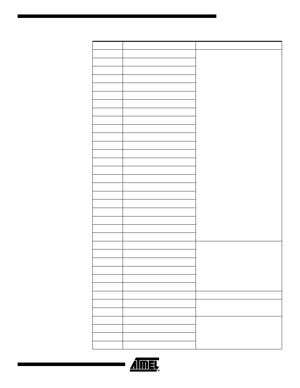
132
PB0.Control
Port B
131
PB0.Pullup_Enable
130
PB1.Data
129
PB1.Control
128
PB1.Pullup_Enable
127
PB2.Data
126
PB2.Control
125
PB2.Pullup_Enable
124
PB3.Data
123
PB3.Control
122
PB3.Pullup_Enable
121
PB4.Data
120
PB4.Control
119
PB4.Pullup_Enable
118
PB5.Data
117
PB5.Control
116
PB5.Pullup_Enable
115
PB6.Data
114
PB6.Control
113
PB6.Pullup_Enable
112
PB7.Data
111
PB7.Control
110
PB7.Pullup_Enable
109
PG3.Data
Port G
108
PG3.Control
107
PG3.Pullup_Enable
106
PG4.Data
105
PG4.Control
104
PG4.Pullup_Enable
103
PG5
(Observe Only)
102
RSTT
Reset Logic
(Observe-only)
101
RSTHV
100
EXTCLKEN
Enable signals for main Clock/Oscillators
99
OSCON
98
RCOSCEN
97
OSC32EN
Table 107. ATmega169 Boundary-scan Order (Continued)
Bit Number
Signal Name
Module
See also other documents in the category Rainbow Electronics Sensors:
- MAX5151 (16 pages)
- MAXQ3108 (64 pages)
- MAX5661 (39 pages)
- MAX6691 (7 pages)
- MAX5362 (12 pages)
- ADC10158 (26 pages)
- MAX8922L (14 pages)
- MAX8596Z (8 pages)
- MAX7491 (18 pages)
- MAX15040 (15 pages)
- MAX5177 (16 pages)
- ADC08138 (22 pages)
- MAX5961 (42 pages)
- T89C51RD2 (86 pages)
- MAX16055 (9 pages)
- MAX6659 (17 pages)
- ADC0820 (20 pages)
- MAX6678 (19 pages)
- MAX8884Z (15 pages)
- MAX16915 (9 pages)
- MAX8620 (18 pages)
- MAX5144 (12 pages)
- MAX6670 (8 pages)
- MAX8760 (39 pages)
- W78C32C (14 pages)
- MX7533 (8 pages)
- MAX8727 (13 pages)
- MAX9053 (15 pages)
- W78C54 (16 pages)
- MAX8614B (15 pages)
- W90N740 (219 pages)
- MAX6626 (13 pages)
- ADC10738 (30 pages)
- MAX17000 (31 pages)
- MAX5051 (21 pages)
- MAXQ1004 (18 pages)
- MAX6871 (51 pages)
- MX7847 (12 pages)
- MAX6608 (6 pages)
- MAX17083 (15 pages)
- MAX6641 (17 pages)
- MAX5251 (16 pages)
- MAX6338 (8 pages)
- MAX6690 (16 pages)
- MAX8668 (18 pages)