Crystal oscillator, Atmega169v/l – Rainbow Electronics Atmega169L User Manual
Page 25
25
ATmega169V/L
2514A–AVR–08/02
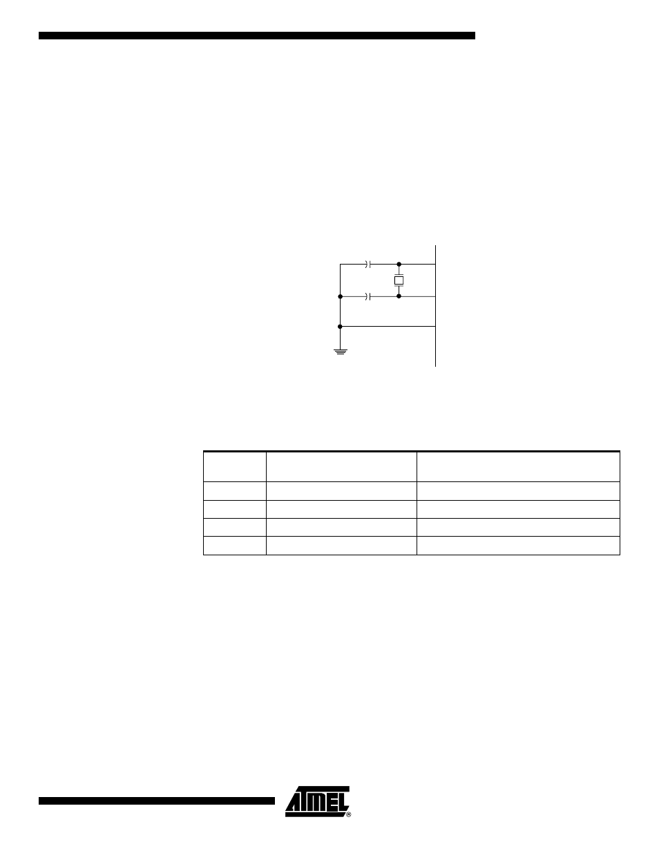
Crystal Oscillator
XTAL1 and XTAL2 are input and output, respectively, of an inverting amplifier which can
be configured for use as an On-chip Oscillator, as shown in Figure 12. Either a quartz
crystal or a ceramic resonator may be used.
C1 and C2 should always be equal for both crystals and resonators. The optimal value
of the capacitors depends on the crystal or resonator in use, the amount of stray capac-
itance, and the electromagnetic noise of the environment. Some initial guidelines for
choosing capacitors for use with crystals are given in Table 4. For ceramic resonators,
the capacitor values given by the manufacturer should be used. For more information on
how to choose capacitors and other details on Oscillator operation, refer to the Multi-
purpose Oscillator Application Note.
Figure 12. Crystal Oscillator Connections
The Oscillator can operate in three different modes, each optimized for a specific fre-
quency range. The operating mode is selected by the fuses CKSEL3..1 as shown in
Table 4.
Notes:
1. The frequency ranges are preliminary values. Actual values are TBD.
2. This option should not be used with crystals, only with ceramic resonators.
The CKSEL0 Fuse together with the SUT1..0 Fuses select the start-up times as shown
in Table 5.
Table 4. Crystal Oscillator Operating Modes
CKSEL3..1
Frequency Range
(1)
(MHz)
Recommended Range for Capacitors C1
and C2 for Use with Crystals (pF)
100
(2)
0.4 - 0.9
–
101
0.9 - 3.0
12 - 22
110
3.0 - 8.0
12 - 22
111
8.0 -
12 - 22
XTAL2
XTAL1
GND
C2
C1