Usart control and status register c – ucsrc, Atmega169v/l – Rainbow Electronics Atmega169L User Manual
Page 171
171
ATmega169V/L
2514A–AVR–08/02
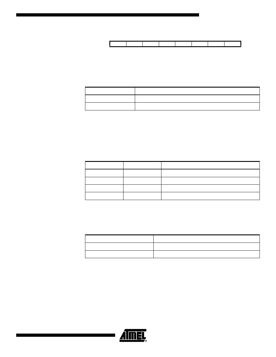
USART Control and Status
Register C – UCSRC
• Bit 6 – UMSEL: USART Mode Select
This bit selects between asynchronous and synchronous mode of operation.
• Bit 5:4 – UPM1:0: Parity Mode
These bits enable and set type of parity generation and check. If enabled, the Transmit-
ter will automatically generate and send the parity of the transmitted data bits within
each frame. The Receiver will generate a parity value for the incoming data and com-
pare it to the UPM0 setting. If a mismatch is detected, the UPE Flag in UCSRA will be
set.
• Bit 3 – USBS: Stop Bit Select
This bit selects the number of stop bits to be inserted by the Transmitter. The Receiver
ignores this setting.
Bit
7
6
5
4
3
2
1
0
–
UMSEL
UPM1
UPM0
USBS
UCSZ1
UCSZ0
UCPOL
UCSRC
Read/Write
R
R/W
R/W
R/W
R/W
R/W
R/W
R/W
Initial Value
0
0
0
0
0
1
1
0
Table 74. UMSEL Bit Settings
UMSEL
Mode
0
Asynchronous Operation
1
Synchronous Operation
Table 75. UPM Bits Settings
UPM1
UPM0
Parity Mode
0
0
Disabled
0
1
Reserved
1
0
Enabled, Even Parity
1
1
Enabled, Odd Parity
Table 76. USBS Bit Settings
USBS
Stop Bit(s)
0
1-bit
1
2-bit