Timer/counter timing diagrams, Atmega169v/l – Rainbow Electronics Atmega169L User Manual
Page 132
132
ATmega169V/L
2514A–AVR–08/02
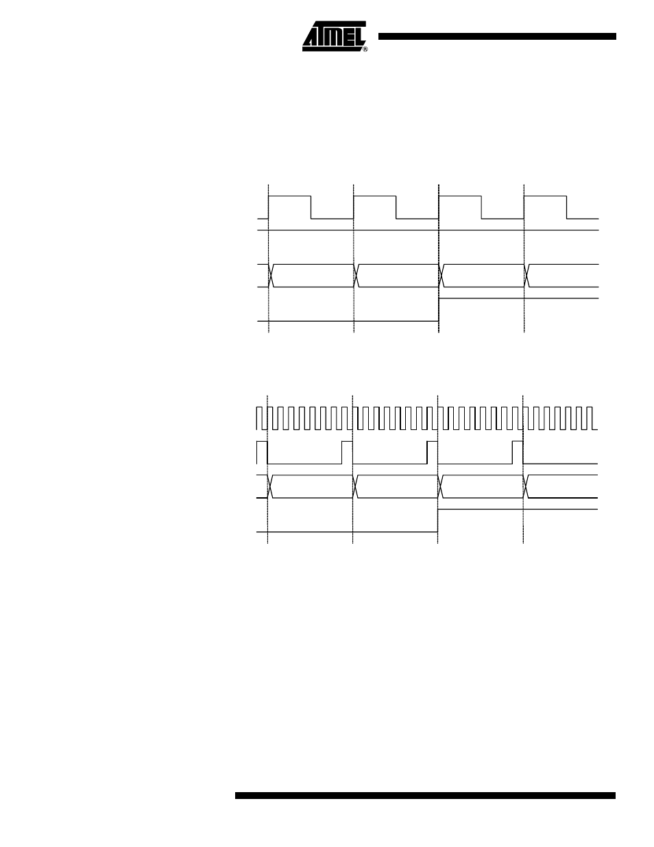
Timer/Counter Timing
Diagrams
The following figures show the Timer/Counter in synchronous mode, and the timer clock
(clk
T2
) is therefore shown as a clock enable signal. In asynchronous mode, clk
I/O
should
be replaced by the Timer/Counter Oscillator clock. The figures include information on
when interrupt flags are set. Figure 59 contains timing data for basic Timer/Counter
operation. The figure shows the count sequence close to the MAX value in all modes
other than phase correct PWM mode.
Figure 59. Timer/Counter Timing Diagram, no Prescaling
Figure 60 shows the same timing data, but with the prescaler enabled.
Figure 60. Timer/Counter Timing Diagram, with Prescaler (f
clk_I/O
/8)
Figure 61 shows the setting of OCF2A in all modes except CTC mode.
clk
Tn
(clk
I/O
/1)
TOVn
clk
I/O
TCNTn
MAX - 1
MAX
BOTTOM
BOTTOM + 1
TOVn
TCNTn
MAX - 1
MAX
BOTTOM
BOTTOM + 1
clk
I/O
clk
Tn
(clk
I/O
/8)
- MAX5151 (16 pages)
- MAXQ3108 (64 pages)
- MAX5661 (39 pages)
- MAX6691 (7 pages)
- MAX5362 (12 pages)
- ADC10158 (26 pages)
- MAX8922L (14 pages)
- MAX8596Z (8 pages)
- MAX7491 (18 pages)
- MAX15040 (15 pages)
- MAX5177 (16 pages)
- ADC08138 (22 pages)
- MAX5961 (42 pages)
- T89C51RD2 (86 pages)
- MAX16055 (9 pages)
- MAX6659 (17 pages)
- ADC0820 (20 pages)
- MAX6678 (19 pages)
- MAX8884Z (15 pages)
- MAX16915 (9 pages)
- MAX8620 (18 pages)
- MAX5144 (12 pages)
- MAX6670 (8 pages)
- MAX8760 (39 pages)
- W78C32C (14 pages)
- MX7533 (8 pages)
- MAX8727 (13 pages)
- MAX9053 (15 pages)
- W78C54 (16 pages)
- MAX8614B (15 pages)
- W90N740 (219 pages)
- MAX6626 (13 pages)
- ADC10738 (30 pages)
- MAX17000 (31 pages)
- MAX5051 (21 pages)
- MAXQ1004 (18 pages)
- MAX6871 (51 pages)
- MX7847 (12 pages)
- MAX6608 (6 pages)
- MAX17083 (15 pages)
- MAX6641 (17 pages)
- MAX5251 (16 pages)
- MAX6338 (8 pages)
- MAX6690 (16 pages)
- MAX8668 (18 pages)