Lcd controller, Features, Overview – Rainbow Electronics Atmega169L User Manual
Page 209: Definitions, Atmega169v/l
209
ATmega169V/L
2514A–AVR–08/02
LCD Controller
The LCD Controller/driver is intended for monochrome passive liquid crystal display
(LCD) with up to four common terminals and up to 25 segment terminals.
Features
•
Display Capacity of 25 Segment and Four Common Terminals
•
Latching of Display Data gives Full Freedom in Register Update
•
Support Static, 1/2, 1/3 and 1/4 Duty
•
Support Static, 1/2, 1/3 Bias
•
Display Possible in Power-save Mode for Low Power Consumption
•
Low Power Waveform Software Selectable
•
Flexible Selection of Frame Frequency
•
Software Selection between System Clock or an External Asynchronous Clock Source
•
On-chip LCD Power Supply, only One External Capacitor needed
•
LCD Output Voltage (Contrast) Software Selectable from 2.6 to 3.35V for V
CC
between
1.8V and 3.6V
•
Equal Source and Sink Capability to Increase LCD Life Time
•
LCD Interrupt Can be Used for Display Data Update or Wake-up from Sleep Mode
•
Segment and Common Pins not Needed for Driving the Display Can be Used as Ordinary
I/O Pins
Overview
A simplified block diagram of the LCD Controller/Driver is shown in Figure 96. For the
actual placement of I/O pins, refer to “Pinout ATmega169” on page 2.
An LCD consists of several segments (pixels or complete symbols) which can be visible
or non visible. A segment has two electrodes with liquid crystal between them. When a
voltage above a threshold voltage is applied across the liquid crystal, the segment
becomes visible.
The voltage must alternate to avoid an electrophoresis effect in the liquid crystal, which
degrades the display. Hence the waveform across a segment must not have a DC-
component.
Definitions
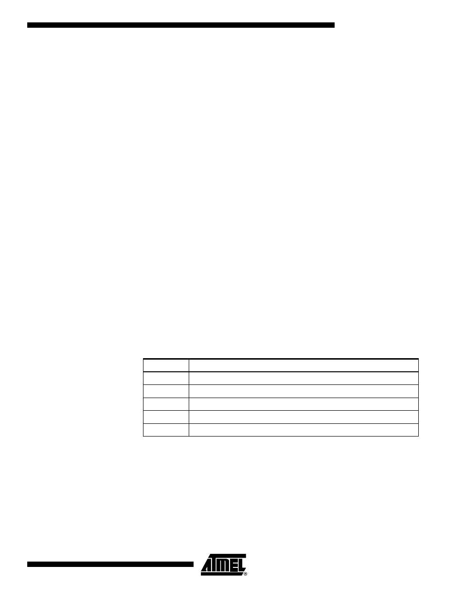
Several terms are used when describing LCD. The definitions in Table 1 are used
throughout this document.
Table 93. Definitions
LCD
A passive display panel with terminals leading directly to a segment
Segment
The least viewing element (pixel) which can be on or off
Common
Denotes how many segments are connected to a segment terminal
Duty
1/(Number of common terminals on a actual LCD display)
Bias
1/(Number of voltage levels used driving a LCD display -1)
Frame Rate
Number of times the LCD segments is energized per second.